Topvex SoftCooler TR09-15 Access control system Installation instructions Document in original language | 208767 · A006 GB
08767 | A006
Contents 1 2 3 4 5 6 7 8 Declaration of Conformity .................................1 Warnings.......................................................2 Refrigerant Control/Reporting ............................2 Product information .........................................2 4.1 General ................................................2 4.2 Technical data .......................................3 4.3 Components .........................................4 4.4 Electrical cabinet ..............................
Declaration of Conformity | 1 Declaration of Conformity Manufacturer Systemair Sverige AB Industrivägen 3 SE-739 30 Skinnskatteberg SWEDEN Office: +46 222 440 00 www.systemair.com hereby confirms that the following products: Cooling unit Topvex SoftCooler TR09 Topvex SoftCooler TR12 Topvex SoftCooler TR15 (The declaration applies only to product in the condition it was delivered in and installed in the facility in accordance with the included installation instructions.
2 | Warnings 2 Warnings The following admonitions will be presented in the different sections of the document. Danger • Make sure that the Mains supply to the unit is disconnected before performing any maintenance or electrical work! • All electrical connections must be carried out by an authorized installer and in accordance with local rules and regulations. • Operation in the refrigerant circuit and handling refrigerants must be performed by certified personnel.
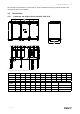
Product information | This instruction is a complement to “Topvex SR 09,11, TR 09-15 Installation instruction” (separate document) and should also be read prior to installation. 4.2 Technical data 4.2.1 Dimensions and weights Topvex SoftCooler TR09-TR15 Fig.
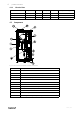
4 | Product information 4.2.2 Electrical data Model Voltage Current (A) Power (W) Fuse, slow Quantity of R410A, kg Topvex SoftCooler TR09 400V 3N~, 50Hz 12 6090 16 4 Topvex SoftCooler TR12 400V 3N~, 50Hz 15 9230 20 4,4 Topvex SoftCooler TR15 400V 3N~, 50Hz 15 9230 20 5,5 4.3 Components Fig.
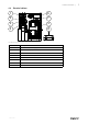
Product information | 4.4 Electrical cabinet 1 6 2 7 3 5 4 8 Fig. 3 Electrical cabinet Position Description 1. Terminal block, mains supply 2. Circuit breaker (MCB) oil heaters 3. Relays 4. Terminal block, internal/external connections 5. Frequency converter with display 6. DC Choke 7. Transformer 24 V 8.
6 | Transport and storage 5 Transport and storage The Topvex SoftCooler should be stored and transported in such a way that it is protected against physical damage that can harm panels, handles etc. It should be covered so that dust, rain and snow cannot enter and damage the unit and its components. The appliance is delivered in one piece containing all necessary components, wrapped in plastic on a pallet for easy transportation.
Installation | 6.3 Installing the unit 6.3.1 Installation Fig.
8 | Installation Fig.
Installation | 6.3.2 Installation procedure Warning Beware of sharp edges during mounting and maintenance. Make sure that a proper lifting device is used. Use protective clothing. 1 Prepare the surface where the unit is to be mounted. Make sure that the surface is flat, levelled and that it supports the weight of the unit. Perform the installation in accordance with local rules and regulations. 2 Lift the unit in place.
10 | Installation A Fig.
Installation | 6.4.1 Assembly the Topvex SoftCooler Fig. 7 Left hand unit Make sure that the sealing stripes and faces of sealing in-between the unit half are undamaged. 1. To get access to the upper mounting screws (M8) remove the rectangular covering plate on top of the Topvex SoftCooler. Place the Topvex SoftCooler in-between the two air handling unit parts and carefully push them together. 2.
12 | Installation Use insulating covering (minimum 100 mm mineral wool) with plastic diffusion barrier. In areas with extremely low outdoor temperatures during the winter, additional insulation must be installed. Total insulation thickness must be at least 150 mm.
Installation | 1. Make sure that all of the cable joints and the two transparent pressure measuring tubes to the extract air fan are correct assembled between the unit parts. 2. Wire the prepared control cable to the Topvex TR electrical cabinet (in the supply air part), use the prepared grommets. Connect the wires to the terminal blocks in the electrical cabinet according to labelling on the wires and the electrical wiring diagram. See also the chapter Internal electrical connections. 3.
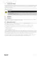
14 | Function Description 7 Function Description DEH DO SS CO ETS OS HPS UC FC CPR RC EF HE EV SF RM Fig. 10 Without by-pass, left hand unit DEH SS ETS DBEH DO CO OS HPS UC CPR FC RC EF HE EV SF RM Fig. 11 With by-pass, left hand unit Position Description EF Extract air fan SF Supply air fan SS Temp. sensor supply air OS Temp. sensor outdoor air ETS Temp.
Function Description | Position Description EV Evaporator CO Condenser HPS Condenser pressure sensor 7.1 General Control unit (UC) senses the temperature via the extract temperature sensor (ETS) and then keep the set extract temperature by sequence controlling the compressor (CPR), heat exchanger (HE) and hot water- /electrical heater (HWL/H, ELH). The temperature sensor in the supply air (SS) is min. and max. limiting the supply air temperature. 7.
16 | Commissioning protocol 8 Commissioning protocol Company: Responsible: 8.1 General Customer: Date: Installation: Object/unit: Item no: Installation address: Model/size Serial no: Designation: 8.2 Installation control Moment Done Note Control report cooling concerning installation established. (Application shall in some cases be done, see chapter 3, Refrigerant Control/Reporting). All unit parts undamaged. Installation carried out according to instructions (see chapter 6.4.
Commissioning protocol | Moment Done Note Select the menu Configuration > Functions > Temperature control: • Set Cooling recovery mode to On Select the menu Configuration > I/O allocation settings > Digital outputs: • Set Signal for Step controller 1 step 1 to DO4 • Set Signal for Step controller 1 step 2 to DO5 Select the menu Configuration > I/O allocation settings > Digital inputs: • Set Signal for Extended operation normal speed to Select I/O (or to any other free DI) • Set Signal for Feedba
18 | Commissioning protocol Moment Done Note Keep the compressor running. Read the below values via the display of the frequency converter, see section ”Frequency converter, quick guide”, in Operating and Maintenance Instructions.
208767 | A006
Phone +46 222 440 00 Fax +46 222 440 99 www.systemair.