
Topvex SoftCooler SR Installation instructions CE208765 A005
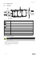
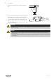

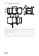
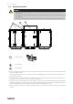

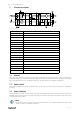

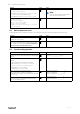
Table Of Contents
- 1 Declaration of Conformity
- 2 Warnings
- 3 Refrigerant Control/Reporting
- 4 Product information
- 5 Transport and storage
- 6 Installation
- 7 Function Description
- 8 Commissioning protocol

Installation |
13
6.7.1 External/Internal connections
See also the enclosed wiring diagram.
Mains supply is the only external connection that should be connected to the Topvex SoftCooler.
Table 1 External connections
Terminal
block
Description
Remark
PE
Ground
400V 3N~, 50Hz
supplied via safety
switch
N N
Earthed neutral (supply voltage)
L1 L1
Phase (supply voltage)
L2 L2
Phase (supply voltage)
L3 L3
Phase (supply voltage)
The already prepared operating cable in Topvex SoftCooler is to be drawn to the electrical cabinet in the supply part of
the Topvex air handling unit and connected to the terminal blocks with the same numbers as the cable markings.
Table 2 Internal connections
Terminal
block
Description
Remark
G G 24V AC
4
DI ref Referens
10
DO ref Referens
15 DO
A signal from control unit for starting Step controller 1 step 1
indicates a cooling demand. The signal controls relay R1 that is
then starting the compressor.
24V AC, 0.5A
74 DI
Alarm indication cooling (Malfunction cooling (SEQ-C).
NO
90
AO ref Reference
94 AO
Control signal from control unit for cooling. Controls the frequency
converter "FC".
0-10V DC
208765 | A005