Topvex SoftCooler SR09, SR11 Access control system Installation instructions Document in original language | 208765 · A005 GB
08765 | A005
Contents 1 2 3 4 5 6 7 8 Declaration of Conformity .................................1 Warnings.......................................................2 Refrigerant Control/Reporting ............................2 Product information .........................................2 4.1 General ................................................2 4.2 Technical data .......................................3 4.3 Components .........................................4 4.4 Electrical cabinet ..............................
Declaration of Conformity | 1 Declaration of Conformity Manufacturer Systemair Sverige AB Industrivägen 3 SE-739 30 Skinnskatteberg SWEDEN Office: +46 222 440 00 www.systemair.com hereby confirms that the following products: Cooling unit Topvex SoftCooler SR09 Topvex SoftCooler SR11 (The declaration applies only to product in the condition it was delivered in and installed in the facility in accordance with the included installation instructions.
2 | Warnings 2 Warnings The following admonitions will be presented in the different sections of the document: Danger • Indicates a potentially or imminently hazardous situation which, if not avoided, could result in death or serious injury. Warning • Indicates a potentially hazardous situation that may result in minor or moderate injuries. Caution • Indicates a risk of damaging the product or prevent optimal operation.
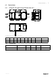
Product information | 4.2 3 Technical data 4.2.1 Dimensions and weights Topvex SoftCooler SR09, SR11 890 890 A 890 F 29 B 225 E D C A C D 29 100 G Fig. 1 Dimensions (mm) SR09, SR11 (Drawn as left hand unit) Model A B C D E F G Weight, kg Weight, TOT SR09 1120 600 400 108 104 260 915 230 665 SR11 1230 800 400 135 165 215 1025 260 695 4.2.
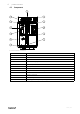
4 | Product information 4.3 Components Fig. 2 Basic components in left hand unit Position Description 1. Compressor 2. Condenser coil 3. Evaporator coil 4. Filter drier with sight glas 5. Electronic expansion valve 6. Drip-tray with drain 7. Water seal 8. Cable grommet for external cabling 9. El. cabinet 10. Frequency converter 11. Pressure/hot gas switches 12.
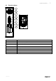
Product information | 4.4 Electrical cabinet 8 6 7 1 2 3 4 5 Fig. 3 Electrical cabinet Position Description 1. Terminal block, mains supply 2. Circuit breaker (MCB) oil heater 3. Relays 4. Terminal block, internal/external connections 5. Frequency converter 6. DC choke 7. 24V transformer 8.
6 | Transport and storage 5 Transport and storage The Topvex SoftCooler should be stored and transported in such a way that it is protected against physical damage that can harm panels, handles etc. It should be covered so that dust, rain and snow cannot enter and damage the unit and its components. The appliance is delivered in one piece containing all necessary components, wrapped in plastic on a pallet for easy transportation.
Installation | 6.3 Installing the unit 6.3.1 Installation Fig. 4 Installation, left hand unit Position Description Supply Exhaust Outdoor Extract 1. VAV pressure transmitter supply air (accessories) 2. VAV pressure transmitter extract air (accessories) 3. Damper and motor exhaust air (accessories) 4. Damper and motor outside air (accessories) 5. Sensor supply air 6. Topvex SoftCooler SR 6.3.2 Installation procedure Warning Beware of sharp edges during mounting and maintenance.
8 | Installation 3 Level the unit with help of the enclosed mounting feet 4 Connect the unit electrically to the mains through the all pole circuit breaker (safety switch), which is enclosed inside the unit on delivery. The wiring between the safety switch and the unit is led through the top of the unit casing directly to the electrical connection box. See enclosed wiring diagram, and chapter 6.7.1, table 1 for more information.
Installation | 6.4 Dividing the Topvex SR air handling unit Before the installation of Topvex SoftCooler SR the Topvex SR has to be divided (figure 5). How to split the unit: Remove the heat exchanger, supply air fan and the extract air filter A. Loosen the cable connectors in the wall B. The two halves of the unit are joined using 4 M10 screws, one in each corner C. Control section D. Heat recovery section E.
10 | Installation 6.4.1 Assembley the Topvex SoftCooler SR Fig. 6 Left hand unit (right hand units are mirrored) Make sure that the sealing stripes and faces in-between the units halves are undamaged. Place the SoftCooler between the two air handling units parts and carefully push them completely together. The SoftCooler is joined to the air handling parts by 4 M10 screws, one in each corner. 1.
Installation | 6.5 Condensation and Heat Insulation Outdoor air duct and discharge ducts must always be well insulated against condensation. Correct insulation installation on ducts connected to the unit is especially important. All ducts installed in cold rooms/areas must be well insulated. Use insulating covering (minimum 100 mm mineral wool) with plastic diffusion barrier. In areas with extremely low outdoor temperatures during the winter, additional insulation must be installed.
12 | Installation 6.7 Electrical connection Danger • Make sure that the Mains supply to the unit is disconnected before performing any maintenance or electrical work! • All electrical connections must be carried out by an authorized installer and in accordance with local rules and regulations. • Operation in the refrigerant cycle and handling refrigerants must be performed by certified personnel. Fig. 9 Electrical connection, left hand unit Cable fastener Control cable Power supply 1.
Installation | 6.7.1 External/Internal connections See also the enclosed wiring diagram. Mains supply is the only external connection that should be connected to the Topvex SoftCooler.
14 | Function Description 7 Function Description CO RC HPS CPR FC HE EV RM Fig. 10 Left hand unit Position Description EF Extract air fan SF Supply air fan SS Temp. sensor supply air OS Temp. sensor outdoor air ETS Temp.
Commissioning protocol | 8 Commissioning protocol Company: Responsible: 8.1 General Customer: Date: Installation: Object/unit: Item no: Installation address: Model/size Serial no: Designation: 8.2 Installation protocol Moment Done Note Control report cooling concerning installation established. (Application shall in some cases be done, see chapter 3, Refrigerant Control/Reporting). All unit parts undamaged. Installation carried out according to instructions (see chapter 6.4.
16 | Commissioning protocol Moment Done Note Select the menu Configuration > I/O allocation settings > Digital inputs: Note: • Set signal for Extended operation normal speed to Select I/O (or to any other free DI) Note: DI4 cannot be used for extended run when Topvex SoftCooler is used.
Commissioning protocol | Moment Done Note Keep the compressor running. Read the below values via the display of the frequency converter, see section ”Frequency converter, quick guide”, in Operating and Maintenance Instructions.
208765 | A005
208765 | A005
Phone +46 222 440 00 Fax +46 222 440 99 www.systemair.