Topvex SoftCooler SR09, SR11 Access control system Operation and Maintenance Instructions Document in original language | 208766 · A003 GB
08766 | A003
Contents 1 2 3 4 5 6 7 8 Warnings.......................................................1 Product description..........................................1 2.1 Components .........................................1 2.2 Electrical cabinet ....................................2 Installing the unit.............................................3 3.1 Installation............................................3 Refrigerant Control/Reporting ............................3 Function Description ..........................
Warnings | 1 Warnings The following admonitions will be presented in the different sections of the document. Danger • Make sure that the Mains supply to the unit is disconnected before performing any maintenance or electrical work! • All electrical connections must be carried out by an authorized installer and in accordance with local rules and regulations. • Operation in the refrigerant circuit and handling refrigerants must be performed by certified personnel.
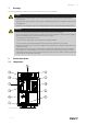
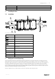
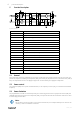
2 | Product description Position Description 1. Compressor 2. Condenser coil 3. Evaporator coil 4. Filter drier with sight glas 5. Electronic expansion valve 6. Drip-tray with drain 7. Water seal 8. Cable grommet for external cabling 9. El. cabinet 10. Frequency converter 11. Pressure/hot gas switches 12. Measuring points refrigerant system high/low 2.2 Electrical cabinet 8 6 7 1 2 3 4 5 Fig. 2 Electrical cabinet Position Description 1. Terminal block, mains supply 2.
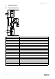
Installing the unit | Position Description 7. 24V transformer 8. LCD display 3 Installing the unit 3.1 Installation Fig. 3 Installation, left hand unit Position Description Supply Exhaust Outdoor Extract 1. VAV pressure transmitter supply air (accessories) 2. VAV pressure transmitter extract air (accessories) 3. Damper and motor exhaust air (accessories) 4. Damper and motor outside air (accessories) 5. Sensor supply air 6.
4 | Function Description 5 Function Description CO RC HPS CPR FC HE EV RM Fig. 4 Left hand unit Position Description EF Extract air fan SF Supply air fan SS Temp. sensor supply air OS Temp. sensor outdoor air ETS Temp.
Cooling flow chart | 6 Cooling flow chart 6.
6 | Cooling flow chart The refrigerant is circulated in a completely closed system in the following order: Evaporator, Compressor, Condenser, and last expansion valve. The compressor keeps a low pressure in the evaporator, the refrigerants boiling point is thereby lowered and the incoming refrigerants from the expansion valve is vaporized (boiling) with absorption of heat as a result. The heat is taken from the supply air when passing the evaporator - supply air temperature is lowered.
Cooling flow chart | 6.2.2.1.1User interface • Bell symbol Display the list of active alarms • Prg Enter the main menu tree • Esc Return to the previous screen • Up arrow Scroll a list upwards or increase the value shown on the display • Enter arrow Enter the selected submenu or confirm the set value • Down arrow Scroll a list down wards or decrease the value shown on the display 6.2.2.1.2PGD1 Menu From this mask you have access to the specific menu dedicated to the Power+ inverter parameters.
8 | Cooling flow chart This mask permits to select the compressor model controlled by Power+. Every change must be followed by the “Set defaults” command to send the new parameters values to the Power +. For specific particular purpose, it is possible to save as “Custom” a special configuration made by changing some parameter of the characteristic ones of a compressor model. N.B.
Cooling flow chart | Configuration of BLDC motor type. The base frequency is the frequency at which the maximum voltage is applied. The base voltage is the maximum voltage applied to the motor. The rated current is the current at full load. The power factor is not used in the BLDC motor type. Maximum current is set at 100%. Frequency step values of the start-up speed profile management: the function is disabled as the starting up is fully controlled by FLSTDmCOMM software installed on the PCOOEM +.
10 | Cooling flow chart These parameters optimize the initial start-up phase of the motor and the relative estimate of the position and the motor speed. Special function settings to perform the direct writing of a specified parameter new value into Power+. 6.2.3 Power controlling Control unit in the air handling unit gives a demand signal (Cooling (SEQ-C), 0-10V DC) in proportion to the current cooling demand in the extract air (or room).
Maintenance | 7 Maintenance Caution Maintenance of the Topvex SoftCooler is of great importance for the whole installations environmental influence, operating economy, durability, security and functions. Read the Warnings chapter 1 and Refrigerant Control/Reporting chapter 4 before doing any work on the SoftCooler unit. Maintenance should be carried out two times a year, apart from general cleaning the following should be done: 1.
12 | Alarms 8 Alarms When an alarm is activated a message is displayed, the corresponding LED comes on and where necessary the alarm relay is activated. The alarms can be divided into three categories: • Serious unit alarms (these stop the compressor). • Alarms that stop one or more functions of the system. • Other alarms (signal only or “warnings”) that do not stop any function, but rather warn the user that certain thresholds have been exceeded, for example.
Alarms | Alarms cont'd Alarm code Display description Reset Delay Alarm relay Action Manual Immediate Yes Off compressor Alarms Power+ n°1 0. No fault 1. Overcurrent 2. Motor overload 3. Overvoltage 4. Undervoltage 5. Drive overT 6. Drive underT 7. Overcurrent HW 8. Motor overtemp. 9. Reserved 10. CPU error 11. Param. default AL06 12. DC bus ripple 13. Data comms fault 14. Drive thermistor 15. Autotune fault 16. Drive disabled 17. Motor phase 18. Fan fault 19. Speed fault 20. PFC failure 21. 22.
14 | Alarms Alarms cont'd Alarm code Display description Reset Delay Alarm relay Action AL20 Pressure Probe U5 faulty or disconnected Automatic 60 sec Yes Off compressor Pressure Probe U6 faulty or disconnected Automatic 60 sec Yes Off compressor 60 sec Yes Off compressor Yes Lock defrost AL21 AL22 Pressure Probe U7 faulty or disconnected Automatic AL23 Defrost ended by max time duration Automatic AL24 BMS offline (bit unchanged) Automatic 20 se Yes Depends on setting AL25
208766 | A003
Phone +46 222 440 00 Fax +46 222 440 99 www.systemair.