
Installation Instruction


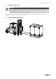
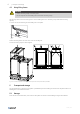

Table Of Contents
- 1 Product information
- 2 Overview
- 3 Warnings
- 4 Unloading from trailer
- 5 Transport and storage
- 6 Unpacking
- 7 Duct connections
- 8 Internal components
- 9 Installation
- 10 Purge sector
- 11 Electrical connections
- 12 Connect the water heating coil
- 13 Access control system
- 14 Connect accessories in Control unit CU27-C
- 15 Dimension and weight
- 16 Technical data
- 17 Additional equipment
- 18 Disposal
- 19 EU Declaration of Conformity
- 20 UK Declaration of Conformity

Product information |
1
1 Product information
This manual includes the information required for installing the heat recovery unit type Topvex SR, TR manufactured by
Systemair Sverige AB. The units include the following model options:
The air handling units is delivered with airflow control CAV (Constant Air Volume).
Side connected units:
Topvex SR20, Topvex SR25, Topvex SR35, Topvex SR60, Topvex SR70, Topvex SR80, Topvex SR100
Weather protection and built-in Access control cabinet (ODK)
Top connected units:
Topvex TR20, Topvex TR25, Topvex TR35, Topvex TR60, Topvex TR70, Topvex TR80
Options:
The air handling units are delivered with the internal electrical cabinet and supply air on right (R) or left (L) side when
viewed from the access side.
Heater options are electrical (EL), hot water (HW) or none (None).
Defrosting options are bypass defrosting (B) or section defrosting (S).
Fan impeller options are composite (standard) or aluminium (M0).
EL heater options
SR/TR20
1,4 kW 5,2 kW
SR/TR25 1,4 kW 5,2 kW
SR/TR35
3,5 kW 7,1 kW
SR/TR60 3,5 kW 7,1 kW 10,4 kW
SR/TR70
3,5 kW 10,4 kW 14,2 kW
SR80
5,2 kW 12,3 kW 19,4 kW
TR80
5,2 kW 12,3kW 19,4 kW
SR100
7,1 kW 15,7 kW 24,6 kW
HW heater options:
HWH (High power) or HWL (Low power)
Type designation example Topvex TR60 HWH-L
Topvex TR 60 HWH -L
Unit name
Top connected
Size
Hot water heater (High)
Left hand unit
254050 | A004