
OPERATION AND MAINTENANCE INSTRUCTION TOPVEX SR TR 254051A003


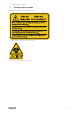
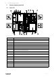
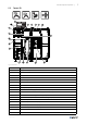
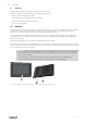
Table Of Contents
- 1 Overview
- 2 Warnings
- 3 Warnings signs on product
- 4 Product description
- 5 Internal components position
- 6 Start up
- 7 Operation
- 8 Maintenance
- 8.1 Maintenance intervals
- 8.2 How to replace supply/extract air filter
- 8.3 How to clean NaviPad
- 8.4 How to clean the heat exchanger
- 8.5 Control of the heat exchanger
- 8.6 How to clean fans
- 8.7 How to clean hot water heating coil
- 8.8 How to clean electric heating coil
- 8.9 How to clean the extract air louvres and inlet diffusers
- 8.10 Clean the outdoor air intake
- 8.11 How to clean the duct system
- 8.12 Where to reset tripped fuses
- 8.13 How to reset the manual overheat protection (EL units)
- 8.14 How to replace the fan module
- 8.15 How to replace the heat exchanger
- 8.16 Change the internal battery in control unit CU27–C
- 9 Troubleshooting
- 10 Alarms
- 11 Service
- 12 General conditions

Product description |
3
4 Product description
Modbus controls and monitors fans, pressure sensors
and heat exchangers.
4.1 Supply and extract air fans
The fans have external rotor motors of EC type which are
steplessly controlled individually by setting the control
signal to a fixed value. It is possible to program the speed
in 3 steps (high/normal/low) depending on the program-
ming of the week schedule. The motor bearings are
maintenance free. It is possible to remove the fans for
cleaning, see chapter 8 for more information.
4.2 Pressure transmitter fans/filters
Two pressure transmitters are installed, each of the
transmitters has two sensors. One sensor measure the
differential pressure over the inlet cone of the fan impel-
lers to maintain the airflow at constant level (CAV func-
tion as standard). The other sensor measure the
differential pressure over the supply and extract air fil-
ters. When the pressure drop reaches the set value, an
alarm is triggered in Access control unit, which indicates
that the filter needs to be replaced.
4.3 Supply and extract air filters
The filters are of bag filter type with filter quality ePM1
60% (F7) for the supply air filter and ePM10 60% (M5)
for the extract air filter. The filters need to be replaced
when polluted. We recommend ordering original filters
from Systemair.
4.4 Heat exchanger
The heat exchanger is a belt driven rotating heat ex-
changer. The operation of the heat exchanger is auto-
matic and depends on the set temperature. An extra
driving belt is included on the rotor on delivery.
4.4.1 VDI 6022 Hygiene standard
If an operation stop of the air handling unit for more than
48 hours is planed, we advise against using cooling re-
covery. This is to avoid microbial growth in eventual con-
densation water in the supply air.
4.5 Temperature sensor
4 temperature sensors (PT1000) are included in the unit
from factory. The sensors are as follows:
• Supply air sensor
• Extract air temperature sensor
• Outdoor air temperature sensor
• Efficiency temperature sensor
The supply air sensor is loosely delivered with the unit
and needs to be installed in the supply air duct externally
from the unit. See Installation instructions for more
information.
4.6 Electric heating coil
In air handling units with built in electrical heater the
heating rods are located after the supply air fan in the air-
flow direction. The material is stainless steel. The electri-
cal heating coil has both automatic and manual
overheating protection. Reset the manual overheat pro-
tection by pushing the red button on top of the electrical
heater frame (figure 6). The electrical heater is mechani-
cally interlocked by an air flow sensor in the supply air.
The power demand of the electric heating coil is con-
trolled by Access control unit. The heat is controlled step-
lessly by a TTC triac control according to the selected
control function that is set in NaviPad control panel.
4.7 Water heating coil
In air handling units with built in water heating coil the
hot water coil is located next to the supply air connection.
The hot water coil can be either HWL (hot water coil, low
power) or HWH (hot water coil, high power). The coil ma-
terial is copper piping with a frame of galvanized sheet
steel and aluminium fins. The coil is equipped with vent-
ing and immersion sensor for frost protection.
4.8 Access control cabinet
Access control cabinet contains the control unit CU27-C
and terminals to connect the control panel and
accessories.
It is possible to remove the cabinet and mount it in a suit-
able location, a control cabinet kit is available as an
accessory.
254051 | A003