CAP-F-N Multi Nozzle Diffuser Handbook
/32 | CAP-F-N Table of Contents Description . . . . . . . . . . . . . . . . . . . . . . . . . . . . . . . . . . . . . . . . . . . . . . . . . . . . . . . . 3 Setup Possibilities . . . . . . . . . . . . . . . . . . . . . . . . . . . . . . . . . . . . . . . . . . . . . . . . . . . .5 Dimensions & Weights . . . . . . . . . . . . . . . . . . . . . . . . . . . . . . . . . . . . . . . . . . . . . . . . . . 6 Ordering Codes . . . . . . . . . . . . . . . . . . . . . . . . . . . . . . . . . . . . . . . . . . . .
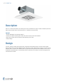
/32 | CAP-F-N Description CAP-F-N is a multi-nozzle diffuser with a backing box, mainly intended for air supply in comfort ventilation systems for offices, shops, medical rooms, school classrooms, etc., installed in T-bar false ceiling.
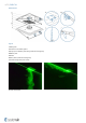
/32 | CAP-F-N Product Parts Legend 1 Backing box 2 Connection with rubber gasket 3 Spring clips for diffuser plate fixing (inside the backing box) 4 Diffuser plate 5 Nozzles 6 Safety cable (inside the backing box) 7 Commissioning tubes pull cut-outs Air flow visualisation
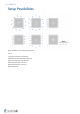
/32 | CAP-F-N Setup Possibilities Nozzle adjustments and resulting air flow pattern Legend 1 Tangential horizontal swirl discharge 2 Radial horizontal omnidirectional discharge 3 Horizontal discharge, single direction 4 Horizontal discharge, 2 directions 5 Horizontal discharge, 3 directions 6 Vertical discharge
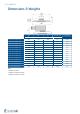
/32 | CAP-F-N Dimensions & Weights W øD H2 m (CAP-F-N) mm m (THOR-F) kg CAP-F-N-125-600-16* 595 124 189 5,3 3,8 CAP-F-N-125-625-16* 620 124 189 5,7 3,8 CAP-F-N-160-600-16* 595 159 189 6,2 3,7 CAP-F-N-160-625-16* 620 159 189 6,2 3,7 CAP-F-N-200-600-25* 595 199 194 6,2 4,4 CAP-F-N-200-625-25* 620 199 194 6,2 4,4 CAP-F-N-250-600-49* 595 249 211 5 6,1 CAP-F-N-250-625-49* 620 249 211 5,4 6,1 CAP-F-N-315-600-64* 595 314 239 6,2 7,9 CAP-F-N-315-625-64*
/32 | CAP-F-N Ordering Codes Nominal size (connection diameter) 125 160 200 250 315 400 T-bar raster size 600 625 Number of nozzles 16 (for nom. size 125) 25 (for nom. size 160) 36 (for nom. size 200) 49 (for nom. size 250) 81 (for nom. size 315) 81 (for nom. size 400) Surface and nozzle colour SW Signal white (RAL9003, gloss 30%) Example of the Ordering Code CAP-F-N-250-600-49-SW Diffuser CAP-F-N in signal white colour (RAL 9003) with connection diameter 250 mm and 49 nozzles for T-bar raster 600 mm.
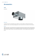
/32 | CAP-F-N Accessories THOR-F Plenum Box Description The THOR-F plenum box is used together with air diffusers for pressure reduction, airflow balancing and sound attenuation as well as for measuring and adjusting the air flow. The plenum box can be used for air inlet and extract. Design THOR-F plenum boxes are manufactured from hot-dip galvanized sheet steel with inlet connection sleeve fitted with a rubber seal tested for air-tightness.
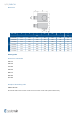
/32 | CAP-F-N Dimensions DN1 - DN2 A B C øD1 øD2 E THOR-F mm 100-125 277 320 159 100-160 277 320 125-200 277 360 160-250 327 200-315 m kg 98 125 132 3,8 159 98 160 132 3,7 169 123 200 147 4,4 450 204 158 250 162 6,1 377 500 259 198 315 172 7,9 250-400 477 565 309 248 400 187 10,8 315-400 577 620 409 313 400 202 15,6 Ordering Codes Nominal size: Inlet-Outlet 100-125 100-160 125-200 160-250 200-315 250-400 315-400 Example of the Ordering Code
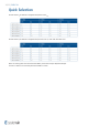
/32 | CAP-F-N Quick Selection Air flow volume qv at different A-weighted sound power levels LWA Air flow volume qv at different A-weighted sound pressure levels LpA with 10m2 absorbtion area NOTE: The working points were measured with THOR-F plenum box and open adjustment damper. For CAP-F-N-400-81 was used with plenum box THOR-F-315-400.
/32 | CAP-F-N Quick Selection Air flow volume qv at different A-weighted sound power levels LWA 25 dB(A) 30 dB(A) 35 dB(A) Item m³/h l/s m³/h l/s m³/h l/s CAP-F-N-125-600-16-SW 76 21 96 27 116 32 CAP-F-N-125-600-16-SW + THOR-F-100-125 66 18 85 24 105 29 CAP-F-N-160-600-16-SW 93 26 121 34 149 41 CAP-F-N-160-600-16-SW + THOR-F-100-160 77 21 98 27 123 34 CAP-F-N-200-600-25-SW 146 41 184 51 221 61 CAP-F-N-200-600-25-SW + THOR-F-125-200 106 29 135 37 169 47
/32 | CAP-F-N Air flow volume qv at different A-weighted sound pressure levels LpA with 10m2 absorbtion area 20 dB(A) 25 dB(A) 30 dB(A) Item m³/h l/s m³/h l/s m³/h l/s CAP-F-N-125-600-16-SW 71 20 93 26 112 31 CAP-F-N-125-600-16-SW + THOR-F-100-125 61 17 81 23 101 28 CAP-F-N-160-600-16-SW 85 24 115 32 143 40 CAP-F-N-160-600-16-SW + THOR-F-100-160 73 20 94 26 118 33 CAP-F-N-200-600-25-SW 137 38 178 49 214 59 CAP-F-N-200-600-25-SW + THOR-F-125-200 100 28 129 3
/32 | CAP-F-N Technical Parameters Legends Ps Pa qv m3/h, Pressure drop LWA dB(A) A-weighted total radiated sound power level LpA dB(A) A-weighted total sound pressure level expressed for 10 m2 room absorption area LW dB Non weighted total sound power level L0,2 m Air throw length with terminal velocity 0,2 m/s Lx m Air throw length calculated for specific terminal velocity X (m/s) Terminal velocity in range of 0,1 m/ s ...
/32 | CAP-F-N Pressure drop & A-weighted total sound power level, depending on air flow volume CAP-F-N-125-600-16-SW + THOR-F-100-125 CAP-F-N-160-600-16-SW + THOR-F-100-160 Pressure drop & A-weighted sound power level in dB(A) Pressure drop & A-weighted sound power level in dB(A) 20 Pa 30 40 l/s 30 40 50 l/s 20 % 45 dB(A) 45 dB(A) 20 % 400 20 Pa 500 40 % 40 % 300 40 dB(A) 35 dB(A) 40 dB(A) 200 80 % 25 dB(A) 100 250 60 % 30 dB(A) 60 % 35 dB(A) 80 % 30 dB(A) 25 dB(A) 100 %
/32 | CAP-F-N CAP-F-N-200-600-25-SW + THOR-F-125-200 CAP-F-N-250-600-49-SW + THOR-F-160-250 Throw length (terminal velocity 0.2 m/s) Throw length (terminal velocity 0.2 m/s) m 3 m 3 Horizontal Horizontal 1.5 1.
/32 | CAP-F-N CAP-F-N-400-600-81-SW + THOR-F-315-400 CAP-F-N-400-600-81-SW + THOR-F-315-400 Pressure drop & A-weighted sound power level in dB(A) Throw length (terminal velocity 0.2 m/s) 150 Pa 300 200 250 l/s m 5 Horizontal 20 % 45 dB(A) 2.
/32 | CAP-F-N Pressure drop & A-weighted total sound power level, depending on air flow volume, measured without THOR-F plenum box CAP-F-N-125-600-16-SW CAP-F-N-160-600-16-SW Pressure drop & A-weighted sound power level in dB(A) Pressure drop & A-weighted sound power level in dB(A) Pa 20 30 40 50 l/s 15 30 Pa 40 50 60 20 l/s 45 45 16 10 40 40 12 35 35 8 30 5 25 m³/h 80 100 120 140 160 4 180 30 25 m³/h 100 150 200 CAP-F-N-125-600-16-SW CAP-F-N-160-600-16-SW Throw length
/32 | CAP-F-N CAP-F-N-200-600-25-SW CAP-F-N-250-600-49-SW Throw length (terminal velocity 0.2 m/s) Throw length (terminal velocity 0.
/32 | CAP-F-N Installation
/32 | CAP-F-N
/32 | CAP-F-N
/32 | CAP-F-N
/32 | CAP-F-N
/32 | CAP-F-N
/32 | CAP-F-N
/32 | CAP-F-N
/32 | CAP-F-N
/32 | CAP-F-N
/32 | CAP-F-N
/32 | CAP-F-N Transport, Storage and Operation
/32 | CAP-F-N Supplement Any deviations from the technical specifications contained herein and the terms should be discussed with the manufacturer. We reserve the right to make any changes to the product without prior notice, provided that these changes do not affect the quality of the product and the required parameters.Current information on all products is available on design.systemair.com.
Systemair DESIGN • 2021-10-27 • Handbook_CAP_F_THOR_F_en-GB • EE604925-B301-42C9-95D8-888C05B6ADDF • Original instructions