
OPERATION AND MAINTENANCE INSTRUCTION TOPVEX SR TR 254051A003

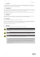
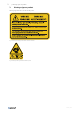
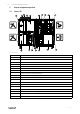
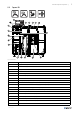
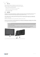
Table Of Contents
- 1 Overview
- 2 Warnings
- 3 Warnings signs on product
- 4 Product description
- 5 Internal components position
- 6 Start up
- 7 Operation
- 8 Maintenance
- 8.1 Maintenance intervals
- 8.2 How to replace supply/extract air filter
- 8.3 How to clean NaviPad
- 8.4 How to clean the heat exchanger
- 8.5 Control of the heat exchanger
- 8.6 How to clean fans
- 8.7 How to clean hot water heating coil
- 8.8 How to clean electric heating coil
- 8.9 How to clean the extract air louvres and inlet diffusers
- 8.10 Clean the outdoor air intake
- 8.11 How to clean the duct system
- 8.12 Where to reset tripped fuses
- 8.13 How to reset the manual overheat protection (EL units)
- 8.14 How to replace the fan module
- 8.15 How to replace the heat exchanger
- 8.16 Change the internal battery in control unit CU27–C
- 9 Troubleshooting
- 10 Alarms
- 11 Service
- 12 General conditions

4
| Internal components position
5 Internal components position
5.1 Topvex SR
Fig. 3 Left hand unit
Position
Description
1
Supply air fan (SF)
2
Extract air fan (EF)
3
Supply air filter
4
Extract air filter
5
Heat exchanger
6
Rotor motor (RM)
7
Internal electrical cabinet
8
Heating coil, EL (ELH) or HWH/HWL (HW)
9
Pressure transmitter supply air fan/extract air filter (PDT1)
10
Pressure transmitter exhaust air fan/supply air filter (PDT2)
11
Pressure transmitter leakage protection (PDT3)
12
Air flow sensor, only for units with electric heating coil (AFS)
13
Water battery connection
14
Extract air temperature sensor (ETS)
15
Efficiency temperature sensor (EFS)
16
Outdoor air temperature sensor (OS)
17
Exhaust air temperature sensor (EHS)
18
Access control cabinet. Figure represent Topvex SR20-60.
254051 | A003