Topvex SR, TR Air handling unit Installation instructions Document in original language | 254050 · A004 GB
© Copyright Systemair AB All rights reserved E&OE Systemair AB reserves the rights to alter their products without notice. This also applies to products already ordered, as long as it does not affect the previously agreed specifications.
Contents 1 2 3 4 5 6 7 8 9 10 11 12 13 Product information .........................................1 Overview ......................................................2 2.1 Intended use .........................................2 2.2 Disclaimer ............................................2 2.3 Warranty ..............................................2 Warnings.......................................................2 Unloading from trailer ......................................3 4.
Product information | 1 Product information This manual includes the information required for installing the heat recovery unit type Topvex SR, TR manufactured by Systemair Sverige AB. The units include the following model options: The air handling units is delivered with airflow control CAV (Constant Air Volume).
2 | Overview 2 Overview This manual includes the information required. If other accessories not included at delivery are in use, read their separate instructions. The key to proper and safe operating is to read this manual thoroughly, use the air handling unit according to given guidelines and follow all safety requirements. 2.
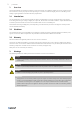
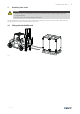
Unloading from trailer | 4 Unloading from trailer Warning • The unit is heavy. Be careful during transport and installation. Risk of injury through pinching. Use protective clothing. • Observe the centre of gravity during transportation. The air handling unit is fastened on the pallet. Unload the air handling unit from the trailer using a forklift truck with enough length on the forks, preferable from the short side. 4.1 Lifting unit with forklift truck Fig.
4 | Transport and storage 4.2 Using lifting frame Warning • Secure the lifting straps on the lifting bars. • Do not compress the air handling unit's chassi with the lifting straps. Use a lifting frame connected to lifting bars in the air handling unit's feet. Use lifting straps with sufficient lifting capacity. 1. Loosen the screws attaching the air handling unit to the pallet Fig. 2 2. Place the lifting bars in the outer feet of the air handling unit. 3. Attach the lifting straps to the lifting bars.
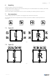
Unpacking | 6 Unpacking Remove the plastic covering the air handling unit. NaviPad, NaviPad holder, supply air sensor, handles, mounting feet are enclosed inside the unit at delivery. One handle is packed on top of the air handling unit. Access control cabinet is loosely packed on the roof of the air handling unit. Mounting position at chapter 9.3. 7 Duct connections Left (L) and Right (R) indicate the position of the supply air when viewed from access side.
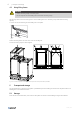
6 | Internal components 8 Internal components 8.1 Topvex SR Fig.
Internal components | 8.2 Topvex TR Fig.
8 | Installation 9 Installation Install Topvex SR, TR preferably in a separate room, for example storage room, laundry room or attic. If it is necessary to install the air handling unit outdoors, Topvex SR ODK versions are weather protected and has the Access control cabinet built-in in the air handling unit. Verify that all ordered equipment are delivered before starting the installation. Report any deviation from the ordered equipment to the supplier of the Systemair products.
Installation | 9.1 Requirements for installation Warning • The unit is heavy. Be careful during transport and installation. Risk of injury through pinching. Use protective clothing. • Connect the ducts or provide with protection to prevent access to the fans through the duct connections. Level the floor surface. It’s important that the air handling unit is completely levelled before it is put into operation. Use the enclosed mounting feet if needed. Adjust the air handling unit's doors if needed.
10 | Installation Location for installation • Place the outdoor air duct in the northern or eastern side of the building, away from other exhaust outlets. • Make sure inspection doors are accessible for maintenance. • Free space for opening of doors and taking out components for service (see dimension drawing). • Avoid placing the unit against a wall. If not possible, insulate carefully. Electrical • Do not cut the mains power supply to the unit if installed in an colder area.
Installation | 9.2 Transport through a standard door (900 mm) 9.2.1 Remove front doors and back side on Topvex SR/TR20-35 Remove the front doors and back side on units Topvex SR/TR20-35 for transportation through a smaller door opening. See respective dimension drawing for dimensions, chapter 15. Caution We advice minimum two persons to remove the back side and the front doors. Remove front doors 1. Remove the hinge covers with a screwdriver. 2. Remove the hinge pin with a bradawl. 3.
12 | Installation Remove back panel 1. Remove the caps covering the hex socket cap screws, 10 pcs. 2. Remove the hex socket cap screws, 10 pcs. 3. Carefully remove the back side. x10 x10 Fig.
Installation | 9.2.2 Divide the air handling unit Divide Topvex SR60-80 and Topvex TR60-80 for transport through smaller openings (min 900 mm) Disconnect the quick connection cables and the 4 connectors (torx 6 mm) and divide the air handling unit. When assembly the parts of the air handling unit, make sure to use the washers (1) with the connector screws. 1 x4 Fig.
14 | Installation 9.3 Attach the Access control cabinet Caution Keep the Access control cabinet including the CU27-C away from direct sunlight. For Topvex SR70–100 and TR20–80, the Access control cabinet is mounted on a bracket. Mount the bracket and Access control cabinet with the supplied screws. The air handling unit has pre-drilled holes for this purpose. For Topvex SR20-60 the Access control cabinet is mounted on top of the air handling unit at delivery.
Installation | 9.4 Insulate the ducts Insulate outdoor and exhaust air ducts against condensation. All ducts installed in cold rooms/areas must be well insulated. Use minimum 100 mm mineral wool insulation covering with plastic diffusion barrier. Install additional insulation in areas with extremely low outdoor temperatures. Caution • Cover the joints with insulation and tape well if the unit is installed in a cold place. • Keep duct connections/duct ends covered during storage and installation.
16 | Installation 9.6 Installation of roof (only Topvex SR ODK versions) Corner brackets, side brackets, roof parts including sheet metal screws for outdoor installation are enclosed at delivery. Fig. 14 1. Place the corner and side brackets on top of the air handling unit. Position the roof to make sure the side brackets are in correct position. Use the side bracket as a template and mark the position. Fasten the brackets with the enclosed screws. 2 1 Fig. 15 2.
Purge sector | 10 Purge sector The figure 16 describes how the purge sector change the direction of the outdoor air to exhaust air and by that rinses the exchanger from remaining of extract air in the rotor material. The air handling units are delivered with the purge sector function deactivated, step 0. Two purge sectors are built in the rotary wheel housing one on each side of the rotor as a preparation for both left and right units.
18 | Electrical connections 11 Electrical connections Danger • Disconnect the mains power supply to the unit before performing any maintenance or electrical work! • Carry out all electrical connections in accordance with local rules and regulation. Electrical connections must be carried out by an authorized installer. 11.1 Connect mains power supply Remove the hatch by unscrewing four screws to the internal electrical cabinet. Fig.
Electrical connections | 230V 3~ 1 400V 3~/230V 1~ 2 Fig. 20 1. 230V 3~ air handling units have a red jumper, L2 is connected to N. 2. 400V 3~/230V 1~ air handling units have a gray jumper, N is connected to N. For detailed information, see the air handling units wiring diagram. 11.2 Electric heating coil Mains power supply to electric heating coil is connected from factory.
20 | Connect the water heating coil 12 Connect the water heating coil Caution Take care not to damage the water battery when connecting water pipes to connectors. Remove the cable grommet and connect the water piping to the female threaded connections. Use a spanner to tighten the connection. The arrows in the figure display the in- and outlet of the hot water. Fig.
Access control system | 13 Access control system Complete control solution with Access control cabinet containing the control unit CU27–C and NaviPad control panel for monitoring and adjusting of the air handling unit’s settings. 13.1 Access control cabinet Danger Disconnect the mains power supply to the unit before moving the Access control cabinet or opening the cabinet's lid. Warning Before obtaining access to terminals, all supply circuits must be disconnected.
22 | Access control system Fig. 23 13.2 Control unit CU27-C Connect NaviPad control panel and all accessories to control unit CU27-C, see chapter 13.3.1 and table 14. Fig. 24 13.3 NaviPad control panel NaviPad is the control panel for Systemair's air handling units and contains several selectable languages. NaviPad is not for outdoor mounting. The protection class of the NaviPad control panel is IP54 and permitted temperature is 0-50° C.
Access control system | 13.3.1 Connect NaviPad Open the Access control cabinet figure 23. Unscrew the connection lid (1) and pull up the lid and comb with plugs that seals the connection area. Brake loose the plug required to connect NaviPad (2). This also apply for other connections to the control unit. Connect NaviPad to the HMI port in the control unit in Access control cabinet. Lead the NaviPad cable in the cable clips (2) and fasten with a cable tie to the strain relief (3).
24 | Access control system 13.3.2 Mount NaviPad holder NaviPad control panel including 3 m cable, holder and screws for mounting are enclosed at delivery. Wall mounting is also possible, use fastenings suitable to the wall’s structure. Mount the holder on suitable location, max distance from control unit 100 m. Use the holder as a drilling template (1). Possible to fasten the NaviPad's cable on the holder's hook (2). Fig.
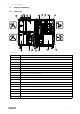
Connect accessories in Control unit CU27-C | 14 Connect accessories in Control unit CU27-C Ext-link – RS485 connection, including 24VDC, for communication with external accessories. BMS – RS485 connection for communication with building management system. Fig. 28 Fig.
| Connect accessories in Control unit CU27-C CU27-C External accessory connection T1:0 1 T1:+ 2 T14:24V +24V T14:AI6 0..10V T14:0V -0V T15:24V +24V T15:0V -0V T16:24V +24V T16:AI4 0..10V T16:0V -0V T27:DI6 NO T27:REF COM T28:DI5 NO T28:REF COM T29:DI4 NO T29:REF COM T30:DI3 NO T30:REF COM T31:DI2 NO T31:REF COM T32:DI1 NO T32:REF COM T61:DO1 L T61:N N T61:PE PE T62:DO2 24V DC Power max. 550mA CO2/Humidity sensor Analog input 0V DC Power 24V DC Power max.
Connect accessories in Control unit CU27-C | CU27-C External accessory connection Notes T71:0V 0V 0V DC Power Analog output T71:AO1 0..10V T71:24V +24V 24V DC Power max. 750mA T72:0V 0V 0V DC Power T72:AO2 0..10V T72:24V +24V T73:0V 0V Valve actuator cooling Analog output 24V DC Power max. 750mA 0V DC Power Changeover Analog output T73:AO3 0..10V T73:24V +24V 24V DC Power max. 750mA T74:0V 0V 0V DC Power T74:AO4 0..
28 | Dimension and weight 15 Dimension and weight 15.1 Topvex SR All dimensions are in mm. Z Y B N A øO 55 118 U F c/c E D P K Q 118 R J C X M L B2 I c/c H G Fig. 30 Topvex SR20, Topvex SR25 B2 = The dimensions with front doors, hinges and back piece disassembled.
Dimension and weight | Z Y B B2 O N W 118 R Q S 118 T P C X M L A 118 F c/c E D K c/c J I Fig. 31 Topvex SR35 B2 = The dimensions with front doors, hinges and back piece disassembled.
30 | Dimension and weight Y Z B O A A2 N H G F 118 W Q R S 118 T P C X M L A2 118 c/c E K c/c J I D Fig.
31 Dimension and weight | 15.2 Topvex TR B B2 Q C O A S N M L 118 R 118 I c/c H G P K J F c/c E D Fig.
32 | Dimension and weight A B A2 S C O A2 N M L 118 T U H G F 118 K c/c J I c/c E R Q P D Fig. 34 Topvex TR60, Topvex TR70, Topvex TR80 A A2 1 B C D c/c E F G H I c/c J Topvex TR60 1786 893 1152 1697 1637 750 800 564 38 978 928 Topvex TR70 1786 893 1312 1858 1637 750 800 564 38 1138 1088 Topvex TR80 1786 893 1513 2097 1637 750 800 564 38 1338 1288 Model 1 Dimension when the air handling units is divided.
Dimension and weight | 15.3 NaviPad Fig. 35 A B C c/c D E F 153 221 40,3 59,4 77,5 3,2 15.4 Access control cabinet Fig.
34 | Technical data 16 Technical data Refer to the data sheet in the online catalogue at www.systemair.com. 17 Additional equipment For information concerning additional external equipment such as valve actuators, motorized dampers, roof units, wall grilles etc. see technical catalogue and their enclosed instructions. For electrical connections of external components see the air handling unit’s wiring diagram and separate documentation. 18 Disposal ♦ Ensure material is recycled.
EU Declaration of Conformity | 19 EU Declaration of Conformity Manufacturer Systemair Sverige AB Industrivägen 3 SE-739 30 Skinnskatteberg Sweden Phone: +46 222 440 00 www.systemair.com The manufacturer hereby confirms that Topvex SR, TR comply with all applicable requirements in the following directives and regulations.
36 | UK Declaration of Conformity 20 UK Declaration of Conformity Manufacturer Systemair Sverige AB Industrivägen 3 SE-739 30 Skinnskatteberg Sweden Phone: +46 222 440 00 www.systemair.com The manufacturer hereby confirms that Topvex SR, TR comply with all applicable requirements in the following directives and regulations.
254050 | A004
Phone +46 222 440 00 www.systemair.