
Communication Manual


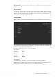
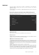


Table Of Contents

Chapter 2 │System integration 6
Chapter 2 System integration
Modbus
Addresses
All addresses starts with 0, and due to that some Master devices starts address with 1 (equal to register)
it’s in that case necessary to add all addresses in this document with +1.
Communication limitations
The Modbus master must wait for a minimum of 3.5 character times (4 ms at 9600 bps) between two
messages.
Baudrate
9600, 14 400, 19 200, 28 800, 38 400, 57 600, 76 800, 115 200 bps
Scale factor Modbus
Real signals could have scale factor according to Scale factor column in tables. In general 10 is used
except for time setting signals which have scale factor 100, and air flow signals which have scale
factor 1. Example, with a scale factor 10 of an temperature Integer value could then be interpreted as
a value with one decimal. Integer, Index and Logic always have scale factor 1.
Unit
Real signal values could have an engineering unit according to Unit-column in tables, where T, Q and
P represent temperature-, flow- and pressure unit according selected preference setting in the
controller.
Modbus wiring, etc.
A protocol like Modbus consists of several layers (OSI-model). The bottom layer is always the
physical layer; the number of wires and signal levels. The next layer describes the communication
digits (number of data bits, stop-bits, parity etc). Next are the layers describing the Modbus-specific
functions (number of digits per message, the meaning of different messages, etc.).
For Modbus, the bottom layer can be RS485, RS422, RS232 or Modbus TCP.
Max. 47 registers
A maximum of 47 registers can be read in one message.
Transmission mode
Access uses the RTU transmission mode for the communication ports. The transmission mode must
be the same in the master unit and the slave units, since Modbus/RTU cannot understand
Modbus/ASCII messages. The configuration parameter Word length is always 8 for Modbus/RTU.