CFC-AG Clean Filtering Cassette
/38 | CFC-AG Table of Contents Description . . . . . . . . . . . . . . . . . . . . . . . . . . . . . . . . . . . . . . . . . . . . . . . . . . . . . . . . 3 Dimensions . . . . . . . . . . . . . . . . . . . . . . . . . . . . . . . . . . . . . . . . . . . . . . . . . . . . . . . . 5 Ordering Codes . . . . . . . . . . . . . . . . . . . . . . . . . . . . . . . . . . . . . . . . . . . . . . . . . . . . . . 6 Accessories . . . . . . . . . . . . . . . . . . . . . . . . . . . . . . . . . . . . . . . . . . . . . .
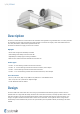
/38 | CFC-AG Description CFC-AG is a cassette used as a terminal device for ventilation with high efficiency particulate filter. It is mainly intended for ventilation of spaces with requirements for high grade of air cleanness like surgery rooms and medical intensive care units, laboratories, industrial clean production sites etc. CFC-AG can be used for air supply as well as for air extract.
/38 | CFC-AG High efficiency filters of the class from E11 up to U18 can be used with CFC-AG. A knife sealing surface is prepared in the cassette to attach the gel gasket of the filter. The cassette is equipped by a pressure measurement nipple for the measurement of the actual filter resistance (clogging detection). The duct connection spigot has a gasket from EPDM.
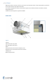
/38 | CFC-AG Dimensions A×A×T *1 A1 øD/DN C 123/125 307 158/160 342 158/160 342 198/200 382 158/160 342 198/200 382 198/200 382 248/250 432 198/200 382 248/250 432 248/250 432 313/315 497 mm 305 × 305 × 80 318 457 × 457 × 80 470 535 × 535 × 80 548 557 × 557 × 80 570 575 × 575 × 80 588 610 × 610 × 80 623 NOTE: 1) The nominal dimensions of CFC-AG are related to exact dimensions (A × A × T) of corresponding filters.
/38 | CFC-AG Ordering Codes Duct connection V Vertical H Horizontal Nominal dimensions (Filter dimensions Length × Width × Thickness) 305 × 305 × 80 457 × 457 × 80 535 × 535 × 80 557 × 557 × 80 575 × 575 × 80 610 × 610 × 80 Connection nominal size DN (mm) (For filter L × H) 125 (for filter 305 × 305) 160 (for filter 305 × 305) 160 (for filter 457 × 457) 200 (for filter 457 × 457) 160 (for filter 535 × 535) 200 (for filter 535 × 535) 200 (for filter 557 × 557) 250 (for filter 557 × 557) 200 (for filter 575
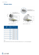
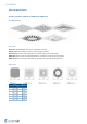
/38 | CFC-AG Accessories PP-CFC-A, CAP-CFC-A, ADQ-CFC-A, VVKR-CFC-A, VVKN-CFC-A Front Diffuser Panels Description PP-CFC-A Perforated diffuser panel mainly intended for air extract CAP-CFC-A Multi nozzle diffuser panel for variable supply air patterns ADQ-CFC-A Diffuser panel with fixed blades for horizontal supply air discharge pattern VVKR-CFC-A Diffuser panel with adjustable blades for variable swirl supply air discharge pattern VVKN-CFC-A Diffuser panel with fixed blades for horizontal swirl supply a
/38 | CFC-AG Ordering Codes Front diffuser panel type PP-CFC-A Perforated panel CAP-CFC-A Multi-nozzle panel ADQ-CFC-A Fixed deflectors panel VVKR-CFC-A Swirl panel with adjustable blades VVKN-CFC-A Swirl panel with fixed blades Nominal dimensions (Filter dimensions length × width) 305 × 305 457 × 457 535 × 535 557 × 557 575 × 575 610 × 610 Surface finish SW Signal white (RAL9003, gloss 30%) RALXXXX Other colour powder coating NOTE: 1) If no Surface finish is defined, RAL9003 wil be delivered.
/38 | CFC-AG APS...CFC-A, APT...CFC-A, APG-CFC-A Adapter Ledges Description The adapter ledges help to adapt the dimensions for installation of the CFC-AG box into the gypsum plaster ceilings, metal plate ceilings or into the T-bar ceilings (see ceiling type, raster in the ordering code). Design The ledges are manufactured from galvanized steel sheet with the same surface finish as the one chosen for the clean filtering cassette (powder paint in RAL9003, eventually other RAL colour).
/38 | CFC-AG Ordering Codes Type of ceiling adapter frame APS625-CFC-A For metal plate ceiling raster 625 APS600-CFC-A For metal plate ceiling raster 600 APT625-CFC-A For T-bar ceiling raster 625 APT600-CFC-A For T-bar ceiling raster 600 APG-CFC-A For plaster board ceiling Nominal dimensions (Filter dimensions length × width) 1 305 × 305 457 × 457 535 × 535 557 × 557 575 × 575 610 × 610 Surface finish SW Signal white (RAL9003, gloss 30%) RALXXXX Other colour powder coating NOTES: 1.
/38 | CFC-AG CFC-GF HEPA Filter with Gel Gasket Description HEPA filter H14 with gel gasket is intended for the clean filtering cassettes. It is a standard initial equipment for CFC-AG. Dimensions Dimensions of the filters (A × A × T) correspond to the clean filtering cassettes nominal dimensions (see dimension table for CFC-AG filter cassettes). The filter nominal thickness is 80 mm, exact thickness is 78 mm.
/38 | CFC-AG Ordering Codes Filter type CFC-GF-14 Filter dimensions 1) A×A×T length × width × thickness (mm) NOTE: 1) Filter dimensions A × A correspond to the nominal dimensions of the cassette. See CFC-AG dimension table Example of Ordering Code CFC-GF-14-305×305×80 HEPA filter with gel gasket, filter class H14, with dimensions 305 mm × 305 mm, thickness 80 mm.
/38 | CFC-AG Quick Selection Initial resistance of the standard H14 filter CFC-GF with nominal thickness 80 mm (exact thickness 78 mm) at different air face velocities 300 ΔP (Pa) 250 200 150 125 100 50 0,3 0,45 0,6 0,8 vF m/s 1,0 1,2 1,5 Quick selection with limitation of critical values, combinations of the clean filter cassettes CFC-AG and front diffuser panels 305 × 305 × 80 457 × 457 × 80 535 × 535 × 80 557 × 557 × 80 575 × 575 × 80 610 × 610 × 80 q (m /h) 70 100 3 PP-CFC-A VVKN-CFC-A
/38 | CFC-AG Quick selection of working points with ∆P = 150 Pa, combinations of the clean filter cassettes CFC-AG and front diffuser panels 305 × 305 × 80 457 × 457 × 80 535 × 535 × 80 557 × 557 × 80 575 × 575 × 80 610 × 610 × 80 q (m /h) 257 420 548 596 641 703 LWA (dB) 33 38 35 36 37 37 L0,2H (m) 7,4 7,7 7,1 5,3 3,8 3,7 q (m /h) 184 356 505 543 587 652 LWA (dB) 41 53 52 46 48 45 L0,2H (m) 5,6 6,9 7,1 5,2 5,6 5,3 q (m /h) 400 500 600 700 750 800 3 PP-CFC
/38 | CFC-AG Technical Parameters Legend L0,2 (m) Lx (m) x (m/s) Air throw length with terminal velocity 0,2 m/s Air throw length calculated for specific terminal velocity Terminal velocity in range of 0,1 m/s ...
/38 | CFC-AG Pressure drop and radiated sound power level dependent on air flow volume Throw length with terminal velocity 0,2 m/s dependent on air flow volume CFC-AG-H-535x535x80-160-SW + ADQ-CFC-A-535x535- CFC-AG-H-557x557x80-200-SW + ADQ-CFC-A-557x557SW + CFC-GF-14-535x535x80 + APG-CFC-A-535x535-SW SW + CFC-GF-14-557x557x80 + APG-CFC-A-557x557-SW Pressure drop & A-weighted sound power level in dB(A) 40 Pa 60 80 Pressure drop & A-weighted sound power level in dB(A) 100 120 l/s Pa 50 100 150 l
/38 | CFC-AG Pressure drop and radiated sound power level dependent on air flow volume Throw length with terminal velocity 0,2 m/s dependent on air flow volume CFC-AG-H-575x575x80-200-SW + ADQ-CFC-A-575x575- CFC-AG-H-610x610x80-250-SW + ADQ-CFC-A-610x610SW + CFC-GF-14-575x575x80 + APG-CFC-A-575x575-SW SW + CFC-GF-14-610x610x78 + APG-CFC-A-610x610-SW Pressure drop & A-weighted sound power level in dB(A) Pa 50 100 Pressure drop & A-weighted sound power level in dB(A) 150 l/s 80 Pa 120 160 200 240
/38 | CFC-AG Pressure drop and radiated sound power level dependent on air flow volume Throw length with terminal velocity 0,2 m/s dependent on air flow volume CFC-AG-H-305x305x80-125-SW + PP-CFC-A-305x305-SW CFC-AG-H-457x457x80-160-SW + PP-CFC-A-457x457-SW + CFC-GF-14-305x305x80 + APG-CFC-A-305x305-SW + CFC-GF-14-457x457x80 + APG-CFC-A-457x457-SW Pressure drop & A-weighted sound power level in dB(A) Pa 20 30 40 50 60 Pressure drop & A-weighted sound power level in dB(A) 70 l/s 150 40 Pa 60 80
/38 | CFC-AG Pressure drop and radiated sound power level dependent on air flow volume Throw length with terminal velocity 0,2 m/s dependent on air flow volume CFC-AG-H-535x535x80-160-SW + PP-CFC-A-535x535-SW CFC-AG-H-557x557x80-200-SW + PP-CFC-A-557x557-SW + CFC-GF-14-535x535x80 + APG-CFC-A-535x535-SW + CFC-GF-14-557x557x80 + APG-CFC-A-557x557-SW Pressure drop & A-weighted sound power level in dB(A) 40 Pa 60 80 Pressure drop & A-weighted sound power level in dB(A) 100 120 l/s 50 Pa 100 150 l/s
/38 | CFC-AG Pressure drop and radiated sound power level dependent on air flow volume Throw length with terminal velocity 0,2 m/s dependent on air flow volume CFC-AG-H-575x575x80-200-SW + PP-CFC-A-575x575-SW CFC-AG-H-610x610x80-250-SW + PP-CFC-A-610x610-SW + CFC-GF-14-575x575x80 + APG-CFC-A-575x575-SW + CFC-GF-14-610x610x78 + APG-CFC-A-610x610-SW Pressure drop & A-weighted sound power level in dB(A) Pa 50 100 Pressure drop & A-weighted sound power level in dB(A) 150 l/s 80 Pa 120 160 200 240
/38 | CFC-AG Pressure drop and radiated sound power level dependent on air flow volume Throw length with terminal velocity 0,2 m/s dependent on air flow volume CFC-AG-H-305x305x80-125-SW + CAP-CFC-A-305x305- CFC-AG-H-457x457x80-160-SW + CAP-CFC-A-457x457SW + CFC-GF-14-305x305x80 + APG-CFC-A-305x305-SW SW + CFC-GF-14-457x457x80 + APG-CFC-A-457x457-SW Pressure drop & A-weighted sound power level in dB(A) Pa 20 30 40 50 60 Pressure drop & A-weighted sound power level in dB(A) 70 l/s 40 Pa 60 80 1
/38 | CFC-AG Pressure drop and radiated sound power level dependent on air flow volume Throw length with terminal velocity 0,2 m/s dependent on air flow volume CFC-AG-H-535x535x80-160-SW + CAP-CFC-A-535x535- CFC-AG-H-557x557x80-200-SW + CAP-CFC-A-557x557SW + CFC-GF-14-535x535x80 + APG-CFC-A-535x535-SW SW + CFC-GF-14-557x557x80 + APG-CFC-A-557x557-SW Pressure drop & A-weighted sound power level in dB(A) 40 Pa 60 80 Pressure drop & A-weighted sound power level in dB(A) 100 120 l/s Pa 50 100 150 l
/38 | CFC-AG Pressure drop and radiated sound power level dependent on air flow volume Throw length with terminal velocity 0,2 m/s dependent on air flow volume CFC-AG-H-575x575x80-200-SW + CAP-CFC-A-575x575- CFC-AG-H-610x610x80-250-SW + CAP-CFC-A-610x610SW + CFC-GF-14-575x575x80 + APG-CFC-A-575x575-SW SW + CFC-GF-14-610x610x78 + APG-CFC-A-610x610-SW Pressure drop & A-weighted sound power level in dB(A) Pa 50 100 Pressure drop & A-weighted sound power level in dB(A) 150 l/s 80 Pa 120 160 200 240
/38 | CFC-AG Pressure drop and radiated sound power level dependent on air flow volume Throw length with terminal velocity 0,2 m/s dependent on air flow volume CFC-AG-H-305x305x80-125-SW + VVKN-CFC-A-305x305- CFC-AG-H-457x457x80-160-SW + VVKN-CFC-A-457x457SW + CFC-GF-14-305x305x80 + APG-CFC-A-305x305-SW SW + CFC-GF-14-457x457x80 + APG-CFC-A-457x457-SW Pressure drop & A-weighted sound power level in dB(A) Pa 20 30 40 50 Pressure drop & A-weighted sound power level in dB(A) 60 200 70 l/s 40 Pa 6
/38 | CFC-AG Pressure drop and radiated sound power level dependent on air flow volume Throw length with terminal velocity 0,2 m/s dependent on air flow volume CFC-AG-H-535x535x80-160-SW + VVKN-CFC-A-535x535- CFC-AG-H-557x557x80-200-SW + VVKN-CFC-A-557x557SW + CFC-GF-14-535x535x80 + APG-CFC-A-535x535-SW SW + CFC-GF-14-557x557x80 + APG-CFC-A-557x557-SW Pressure drop & A-weighted sound power level in dB(A) 40 Pa 60 80 Pressure drop & A-weighted sound power level in dB(A) 100 120 l/s Pa 50 100 150
/38 | CFC-AG Pressure drop and radiated sound power level dependent on air flow volume Throw length with terminal velocity 0,2 m/s dependent on air flow volume CFC-AG-H-575x575x80-200-SW + VVKN-CFC-A-575x575- CFC-AG-H-610x610x80-250-SW + VVKN-CFC-A-610x610SW + CFC-GF-14-575x575x80 + APG-CFC-A-575x575-SW SW + CFC-GF-14-610x610x78 + APG-CFC-A-610x610-SW Pressure drop & A-weighted sound power level in dB(A) Pa 50 100 Pressure drop & A-weighted sound power level in dB(A) 150 l/s 45 160 80 Pa 120 16
/38 | CFC-AG Pressure drop and radiated sound power level dependent on air flow volume Throw length with terminal velocity 0,2 m/s dependent on air flow volume CFC-AG-H-305x305x80-125-SW + VVKR-CFC-A-305x305- CFC-AG-H-457x457x80-160-SW + VVKR-CFC-A-457x457SW + CFC-GF-14-305x305x80 + APG-CFC-A-305x305-SW SW + CFC-GF-14-457x457x80 + APG-CFC-A-457x457-SW Pressure drop & A-weighted sound power level in dB(A) Pa 20 30 40 50 Pressure drop & A-weighted sound power level in dB(A) 60 200 70 l/s 40 160
/38 | CFC-AG Pressure drop and radiated sound power level dependent on air flow volume Throw length with terminal velocity 0,2 m/s dependent on air flow volume CFC-AG-H-535x535x80-160-SW + VVKR-CFC-A-535x535- CFC-AG-H-557x557x80-200-SW + VVKR-CFC-A-557x557SW + CFC-GF-14-535x535x80 + APG-CFC-A-535x535-SW SW + CFC-GF-14-557x557x80 + APG-CFC-A-557x557-SW Pressure drop & A-weighted sound power level in dB(A) 40 Pa 60 80 Pressure drop & A-weighted sound power level in dB(A) 100 120 l/s Pa 50 100 150
/38 | CFC-AG Pressure drop and radiated sound power level dependent on air flow volume Throw length with terminal velocity 0,2 m/s dependent on air flow volume CFC-AG-H-575x575x80-200-SW + VVKR-CFC-A-575x575- CFC-AG-H-610x610x80-250-SW + VVKR-CFC-A-610x610SW + CFC-GF-14-575x575x80 + APG-CFC-A-575x575-SW SW + CFC-GF-14-610x610x78 + APG-CFC-A-610x610-SW Pressure drop & A-weighted sound power level in dB(A) Pa 50 100 Pressure drop & A-weighted sound power level in dB(A) 150 l/s 80 Pa 120 160 200 2
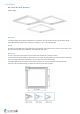
/38 | CFC-AG Installation
/38 | CFC-AG
/38 | CFC-AG
/38 | CFC-AG
/38 | CFC-AG
/38 | CFC-AG Maintenance
/38 | CFC-AG Transport, Storage and Operation
/38 | CFC-AG Supplement Any deviations from the technical specifications contained on our website and the terms should be discussed with the manufacturer. We reserve the right to make any changes to the product without prior notice, provided that these changes do not affect the quality of the product and the required parameters. Current information on all products is available on design.systemair.com.
Systemair DESIGN • 2021-06-09 • Handbook_CFC_AG_en-GB