
Manual Axial fan AW C003


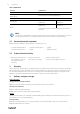
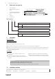
Table Of Contents
- 1 General information
- 2 Important safety information
- 3 Warranty
- 4 Delivery, transport, storage
- 5 Description
- 6 Name plate and type key
- 7 Installation
- 8 Electrical connection
- 9 Commissioning
- 10 Operation
- 11 Troubleshooting/maintenance/repair
- 12 Cleaning
- 13 Deinstallation/dismantling
- 14 Disposal
- 15 Commissioning Report

Electrical connection |
5
8 Electrical connection
Safety information
♦ Observe 2 Important safety information, page 1
♦ Prevent the ingress of water into the connection box.
Connection
♦ Check if the data on the nameplate matches the
connection data.
♦ Complete the electrical connection according to the
circuit diagram.
♦ Connect the cable end in a dry environment.
♦ Install a circuit breaker in the permanent electrical
installation, with a contact opening of at least 3 mm
at each pole.
Protective grounding wire
The protective grounding must have a cross-section equal to or greater than that of the phase conductor.
Residual current circuit breaker
All-current-sensitive residual current circuit breakers are required for use in alternating-current systems with 50/60
Hz, in combination with electronic devices such as EC motors, frequency converters or uninterruptible power supplies
(UPS).
8.1 Wiring diagram
1.Yellow-Green 5. Black
1.
2.
3.
4.
5.
6.
7.
2. Blue (N)
6. Brown
3. Black (L1)
7. Blue
4.Yellow-Green
The thermocontact is internally connected.
8.2 Protecting the motor
Important
Damage to motor due to overcurrent, overload or short circiut.
♦ Lead-out temperature monitors must be integrated in the control circuit in such a way that, if a fault
occurs, the motor cannot switch on again automatically after it has cooled down.
♦ Motor lines and temperature monitor lines should be laid separately on principle.
♦ Without thermal protection: Use a motor protection switch!
Note:
Internally connected thermocontact: no external connection feasible or necessary.
Warning
Risk of injury because of sudden start up of the fan.
Thermost switches switch after triggering by excess temperature and closed independently after cooling
off. The fan can start up during this time.
♦ Consider that the impeller can start up suddenly without resetting the fault.
♦ Observe the 5 rules of electrical safety, see 2.3 5 rules of electrical safety, page 2.
| 003