
SYSVRF AIR EVO HP MINI IM


4
installation manual
All the pictures in this manual are for explanation purpose only.
They may be slightly different from the air conditioner you
purchased(depend on model).The actual shape shall prevail.
NOTE
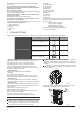
3.3 Moving and installation
Fig.3-7
>
6
0
c m
Fix with bolt
Do not touch the fan with hands or other objects.
Do not lean it more than 45°, and do not lay it sidelong.
Make concrete foundation according to the sepecifications of
the outdoor units.(refer to Fig.3-7)
Fasten the feet of this unit with bolts firmly to prevent it from
collapsing in case of earthquake or strong wind.
(refer to Fig.3-7)
Since the gravity center of the unit is not at its physical center,
so please be careful when lifting it with a sling.
Never hold the inlet of the outdoor unit to prevent it from
deforming.
Table 4-1
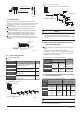
Fig.3-8
The indoor and outdoor connecting pipe interface and power
line outlet
3.4 Water Outlet
Reserve water outlet
Reserve water outlet
Water Outlet
Outlet for power and connecting pipes
(Need to knock open)
(With rubber stopper)
Vavious piping and viring patterns can be selected,such as out from
the front ,the back the side ,and undersurface, etc.˄The follow display
the locations of several piping and wiring knock-out interfaces˅
Front pipe
Back pipe
Side pipe
Bottom pipe
To prevent the refrigerant piping from oxidizing inside when
welding, it is necessary to charge nitrogen, or oxide will chock
the circulation system.
CAUTION
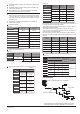
4. INSTALL THE CONNECTING PIPE
Check whether the height drop between the indoor unit and
outdoor unit, the length of refrigerant pipe, and the number of
the bends meet the following requirements:
4.1 Refrigerant piping
Fig.4-1
Large pipe
Four condensed water outlets on the chassis for selection
display as the follow figure:
Please pay attention to avoid the components while connect to
the connecting pipes.
While installing the outdoor unit, pay attention to the installation
place and the drainage pattern;
if it’s installed at the alpine zone, the frozen condensed water will
block up the water outlet, please pull out the rubber stopper of the
reserve water outlet. If that still fails to satisfy for the water draining,
please knock open the other two water outlets, and keep the water
can drain in time.
Pay attention to the knock the reserve water outlet from outside to
inside, and it will be beyond repair after knocking open, please pay
attention to the installation place.
Please do the insect proofing for the knocked out hole, to avoid the
insects coming into the unit and destroy the components.
CAUTION
Side pipe: remove the L-shape metal plate at first, otherwise
wiring is not possible.
Back pipe: please remove the piping support rubber blanket
beside the inner outlet pipe cover of the machine.
Front pipe: cut the frontal hole of the pipe-outlet plate.
Bottom pipe: Knock out the hole from inside to
outside. Do the piping and wiring through this hole. Pay attention that
the large pipe should come out from the largest hole, otherwise the
pipes will be rubbed.
Please do the insect proofing for the hole, to avoid the insects coming
into the unit and destroy the components.
CAUTION
Use soap water or leak detector to check every joint whether leak or
not (Refer to Fig.4-2).Note:
A is low pressure side stop valve
B is high pressure side stop valve
C and D is connecting pipes interface of indoor and outdoor units
4.2 Leak Detection