
SYSVRF AIR EVO HP MINI IM


6
installation manual
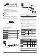
Branch header must be connected with indoor units directly,
the further branch connection is not allowed.
Select branch joint
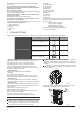
Select the branch joint according to the total designed capacity
of indoor units which it connects to. If this capacity is more than
that of the outdoor unit, then select the connection according to
the outdoor unit.
The selection of branch header depends on the quantity of
branches it connects to.
4
5
6
6
45%~130%
45%~130%
12
14
6 7 45%~130% 16
Outdoor Unit
(kW)
Capacity of
Outdoor unit
(horsepower)
Maximum
Quantity of
Indoor unit
Sum Capacity
of Indoor unit
(horsepower)
0.8
1.25
1.7
2
2.5
3
4
5
22
0.6
18
10.5
36
45
56
120
140
80
Capacity
ranking
Capacity
(horsepower)
Capacity
ranking
Capacity
(horsepower)
Connection method
Flaring
Welding or Flaring
Flaring
Flaring Flaring
Flaring Flaring
12kW
Branch pipe
Indoor unit
14kW
16kW
Flaring Flaring
18kW
Gas side
Liquid side
Table 4-9
Table 4-5
Piping sizes at the branch pipe
1
28
6
160
Flaring
Flaring
Flaring
Flaring
8kW
10.5kW Flaring
Flaring
Welding or Flaring
(The quantity of indoor unit more than or equal to two, each indoor unit
of capacity should be not more than 8.0kW.)
When capacity of indoor unit greater than the sum of 100%, capacity
of indoor unit will be attenuated.
When capacity of indoor unit greater than or equal to the sum of
120%, in order to ensure the effectiveness of machine, and then try to
open the indoor units at different time.
When the capacity of indoor unit is greater than or equal to 16.8kW,
the caliber of primary gas pipe should be augmented from
Φ
16 to
Φ
19.
12.7(Flaring nut)
A≤45
R410A
A≥56
6.4(Flaring nut)
15.9(Flaring nut) 9.5(Flaring nut)
R410A
Gas Side (Φ) Liquid Side (Φ)
Table 4-6
Indoor Unit Capacity
A(x100W)
Refrigerant
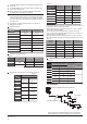
Table 4-10
When outdoor
unit is top
When outdoor
unit is bottom
less than 10
MODEL
(kW)
The max height drop(m)
The length of
refrigerant
pipe(m)
The number
of bends
12
14
16
18
25
25
25
25
20
20
20
20
50
50
50
50
When the outdoor unit connects one indoor unit
The straight distance between the contiguous branchpipes is at
least 0.5m;
The straight distance which the branch pipes connected to the
indoor unit is at least 0.5m;
1
1
1
1
1
1
$
%
'
(
&
D
E
F
H
I
G
/
/
/
/
/
4.6 Illustration
Outdoor Unit((Take Model 160 For Example)
The First Line Branch Pipe
Indoor units
Caution: Suppose in the displayed piping system, the total equi-
valent piping length of air side + liquid side is longer than 90m.
8
10.5
25
25
20
20
50
50
6.5 9 45%~130% 18
8
10.5
45%~130%
45%~130%
4
5
2.5
3
Table 4-8
Fig.4-6
Piping
side
¢ ¢
¢ ¢
¢ ¢
Pipe diameter of outdoor unit's connector(mm)
¢ ¢
¢ ¢
MODEL
(kW)
8
10.5
12
14
16
¢ ¢
18
Table 4-7
Pipe diameter of the connector in the outdoor unit's body
Gas Side Liquid Side