
SYSVRF AIR EVO HP MINI IM


5
installation manual
NOTE
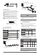
Size of main pipe and corresponding branch joint and branch
header
Table 4-2
Select refrigerant pipe
Fig. 4-3
The unit body
Affiliated heat pump belt
Site pipe side
Cut from upward
4.3 Heat Insulation
Do the heat insulation to the pipes of air side and liquid side
separately. The temperature of the pipes of air side and liquid side
when cooling, for avoiding condensation please do the heat
insulation fully.
The air side pipe should use closed cell foamed insulation
material, which the fire-retardant is B1 grade and the heat
resistance over 120°C.
When the external diameter of copper pipe≤Φ12.7mm, the
thickness of the insulating layer at least more than 15mm;
When the external diameter of copper pipe≥Φ15.9mm, the
thickness of the insulating layer at least more than 20mm.
Please use attached heat-insulating materials do the heat
insulation without clearance for the connecting parts of the indoor
unit pipes.
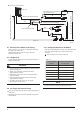
Fig. 4-2
Check point of outdoor unit
Check point of indoor unit
D
A
B
C
Pipe definition
Pipe connect position
The pipe between outdoor unit to the
first branch of indoor unit.
The main pipes of
indoor unit
Code
Indoor unit branch
pipes components
/Њ/
/
DEF
GHI
$%&
'(
The first connect methond
D
E
F
H
I
G
/
/
/
/
/
$
%
&
'
(
NOTE
4.4 Confirmation for the diameters of indoor
unit connecting pipes
$ψ
ŏ$ψ
Total capactiy of
the downstream
inner units
Main pipe size˄mm
˅
Iiquid pipe
¢
¢
¢
Branch Pipe
SYSVRF
JOINT IN 01 2P
¢
R410A Indoor unit connecting pipes diameters
1) R410A Indoor unit connecting pipes diameters 4-3DŽ
2) Example 1˖In the Fig.4-5,The downstream inner units of the
L2,and its total capacity is 28×2˙56
ˈrefers to the Table 4.4,the
air/liquid side of L2 is˖Φ15.9/Φ9.5DŽ
1
1
1
1
1
1
$
%
'
(
&
D
E
F
H
I
G
/
/
/
/
/
The straight distance between copper pipe turning and the contig-
uous branch pipe is at least 0.5m;
air side
PP
liquid si-
de
PP
$ψ
ŏ$ψ
¢ ¢
¢
¢
¢ ¢
¢ ¢
Main pipe size when the tot-
al equivalent piping length
of liquid + air side is <90m
4.4 Connecting method
Main pipe
The branch pipes
of indoor unit
The pipe after the first branch do not
directly connect with the indoor unit.
The pipe after the branch connect with
the indoor unit.
The pipes connect with the main pipeǃ
the branch pipe and the the main pipe
of indoor unit.
The First Line Branch Pipe
Outdoor Unit
The First Line Branch Pipe
Outdoor Unit(T
ake Model 160 for example)
The second connect method
Intdoor Units
Fig. 4-4
Fig. 4-5
The distance between the first branch to the last indoor unit is
more than 15m,choose the second connect method.
The pipe between the indoor unit to the closest branch must less
than 15m.
Table 4-3
Air pipe
R410A outdoor unit connecting pipes diameters
Total capa-
ctiy of The
outdoor
units
Table 4-4
Main pipe size when the tot-
al equivalent piping length
of liquid + air side is ≥90m
air side
PP
liquid si-
de
PP
The first Line
Branch Pipe
The first Line
Branch Pipe
4.5 Confirmation for the diameters of outdoor
unit connecting pipes
SYSVRF
JOINT IN 01 2P
SYSVRF
JOINT IN 01 2P
SYSVRF
JOINT IN 01 2P
SYSVRF
JOINT IN 01 2P
SYSVRF
JOINT IN 0
2 2P