
SYSVRF AIR EVO HP MINI IM


7
installation manual
Main pipe (Please refer to Fig.4-5 and Fig.4-7)
In Fig.4-6, the main pipe L1, the outdoor unit capacity is
16kW, and check the Fig.4-7 to get the size of gas pipe/liquid
pipe is Φ19.1/Φ9.5, and aslo the total equivalent length of liquid
side and gas side pipes is >90m,then check the Fig.4-4 to get
the size of gas pipe/liquid pipe is Φ22.2/Φ9.5, and according to
the maximum value principle, it should apply the Φ22.2/Φ9.5.
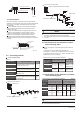
Allowable length and altitude difference of refrigerant pipe
Maximum
Piping(L)
Indoor Unit to Indoor Unit Drop Heihgt(H)
Equivalent Length
Actual Length
or L1+L3+L5+f(The second connect method)
or L3+L5+f(The second connect method)
L1+L2+L3+L4+L5+f(The first connect method)
L2+L3+L4+L5+f(The first connect method)
DEFGH
Total Pipe Length(Actual)
Pipe Length
Pipe Length(from the first line branch
pipe to furhtest indoor unit)(m)
Indoor Unit-Outdoor
Unit Drop Height(H)
Outdoor Unit up
Outdoor Unit Down
Permitted value
ŏP
ŏPδN:θN:θN:θN:ε
ŏPδN:θN:θN:θN:ε
ŏP
ŏP
ŏP
ŏP
Piping
/////
+a+b+c+d+e+f
ŏP
Drop HEIGHT between indoor unit and uutdoor unit
The first cennect method
Indoor Unit
The First Line Branch Pipe
Outdoor unit
D
$
/
/
%
&
'
(
/ / /
E
F
G
H I
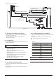
Fig.4-7
Note: When the total equivalent piping length of liquid + gas side is ≥90m, it must increase the size of air side main pipe. Besides, according
to the distance of refrigerant pipe and the over matched state of inner unit, when the capacity is decreasing it still can increase the gas side
main pipe size.
ŏPδN:θN:ε
ŏPδN:θN:ε
Inner branch pipes are a~f, the size selection please refers to
Table4-6. Note: The max. length of the branch pipe should not
longer than 15m.
Indoor unit branch pipe
The main pipes of indoor unit and the indoor unit branch pipe
components
The downstream inner units of the main pipe L2 are N1, N2, and
its total capacity is 28×2=56, the size of pipe L2 isΦ15.9/Φ9.5,
and the branch pipe B should be SYSVRF JOINT IN 01 2P.
The downstream inner units of the main pipe L4 are N3, N4, and
its total capacity is 28×2=56, the size of pipe L4 isΦ15.9/Φ9.5,
and the branch pipe D should be SYSVRF JOINT IN 01 2P.
The downstream inner units of the main pipe L5 are N5, N6, and
its total capacity is 28+22=50, the size of pipe L5 isΦ15.9/Φ9.5,
and the branch pipe E should be SYSVRF JOINT IN 01 2P.
The indoor unit below to the main pipe L3 are N3
N6, and its to-
tal capacity is 28×3+22=106, the size of pipe L3 isΦ15.9/Φ9.5, and
he branch pipe C should be SYSVRF JOINT IN 01 2P.
The indoor unit below to the main pipe A are N1N6, and its to-tal
capacity is 28×5+22=162, and the branch pipe should be SYSVRF
JOINT IN 01 2P, and because the total piping length of liquid + air
side is ≥90m, check Table.4-4, and the first branch pipe should
apply SYSVRF JOINT IN 02 2P, and according to the principle of
maximum value, it should apply SYSVRF JOINT IN 02 2P.
Drop Height
Pipe Length(from the nearest branch
pipe equivalent length(m)
Pipe length(From the nearest branch pipe equivalent length)
Maximum pipe equivalent length
(From the first line branch pipe) Maximum pipe equivalent length
Indoor Unit to Indoor
Unit Drop Heihgt
table 4-11