
SYSVRF JOINT OUT IM


Field pipe Φ25.4 or Φ31.8
(Fix according to machine’s
factory setting pipe size)
Field pipe Φ25.4 or Φ31.8
(Fix according to machine’s
factory setting pipe size)
Field pipe Φ25.4 or Φ31.8
(Fix according to machine’s
factory setting pipe size)
Field pipe
Φ25.4 or Φ31.8
(Fix according to machine’s
factory setting pipe size)
Liquid side pipes
Field elbow bend
(Machine Accessory)
Gas side pipes
Field pipe Φ12.7 or Φ15.9
(Fix according to machine’s
factory setting pipe size)
Field pipe Φ12.7 or Φ15.9
(Fix according to machine’s
factory setting pipe size)
Field
pipe
Φ
12.7 or
Φ
15.9
(Fix according to machine’s
factory setting pipe size)
Field pipe Φ
12.7 or Φ15.9
(Fix according to machine’s
factory setting pipe size)
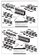
NOTE
1 When numbers in brackets represent the equivalent length of all liquid pipes < 90m, means the
selected pipe size value.
2 It’s advised to use the Max. HP unit as the main unit. See above figure W4 outdoor unit (main unit),
Arranging the units with a sequence of Max. to Min.(i.e. W4>W3>W2>W1).
3 The above figure is only available for the models such as D3,V4 and V4+ series with R410A refrigerant
when they are paralleled connected.
4 Please select T-style three direct links according to user guide of the external packaging bag; please
dumping the redundant T-style three direct links in the accessories and do not use for other purposes.
5 Pipe diameter of outdoor unit :
V4+:8~10HP, Gas/Liquid side:Φ25.4/Φ12.7;12~16HP, Gas/Liquid side:Φ31.8/Φ15.9;
V 4、D3:8~12HP, Gas/Liquid side:Φ25.4/Φ12.7;14~16HP, Gas/Liquid side:Φ31.8/Φ15.9.
6 All the pictures in this manual are for explanation purpose only. They may be slightly different from the
air conditioner you purchased(depend on model).The actual shape shall prevail.
NOTE
1
When numbers in brackets represent the equivalent length of all liquid pipes < 90m, means
the selected pipe size value.
2 It’s advised to use the Max. HP unit as the main unit. See above figure W3 outdoor unit (main unit),
Arranging the units with a sequence of Max. to Min.(i.e. W3>W2>W1).
3 The above figure is only available for the models such as D3,V4 and V4+ series with R410A refrigerant
when they are paralleled connected.
4 Please select T-style three direct links according to user guide of the external packaging bag; please
dumping the redundant T-style three direct links in the accessories and do not use for other purposes.
5 Pipe diameter of outdoor unit :
V4+:8~10HP,
Gas
/Liquid side:
Φ
25.4/
Φ
12.7;12~16HP,
Gas
/Liquid side:
Φ
31.8/
Φ
15.9;
V4、D3:8~12HP,
Gas
/Liquid side:
Φ
25.4/
Φ
12.7;14~16HP,
Gas
/Liquid side:
Φ
31.8/
Φ
15.9.
6 All the pictures in this manual are for explanation purpose only. They may be slightly different from the
air conditioner you purchased(depend on model).The actual shape shall prevail.
W1
W2
W3
W4
W1
W2
W3
W4
W1
W2
W3
W4
W1
W2
W3
W1
W2
W3
W1
W2
W3
W4
W1
W2
W3
W1
W2
W3
W1
W2
W3(Main unit)
W4
W1
W2
W3
W1
W2
W3
Gas side joint
Q5
2
W2
W3
W4(Main unit)
Field pipe Φ38.1
Y1
Y6 Y3
Y2
Y1
Y1
Y7
Y1
Y7
Y1
Y8 Y5
Y4
Y6
Y2
Y1
Y6
Y2
Q1
Q3Q4
Q1
Q1 Q1
Q1
Q1
Q2
Q2
Q2
Q7
Q7
Q5
Q5
Q6
Q1
Q2
Q1
Q2
Q1
Q7
Q4
Q4
Q3
Q3
Q4
Q3
Field pipe, the caliber refer to Table.3
If 34≤W1+W2+W3≤48, i.e. Φ41.3(41.3).
Gas side joint Q1(Two)
Gas side joint
Q7
Gas side joint
Q2
Field pipe Φ15.9
Field pipe Φ15.9
Field pipe Φ15.9
Gas balance pipes 1 M
Flaring connection
Flaring connection
Flaring connection
Field pipe Φ6.4
Field pipe Φ6.4
Gas balance pipes 1 M
Welding
Welding
Welding
Rejoining method for D3 series outdoor unit
Rejoining method for V4/V4+ series outdoor unit
Gas balance pipes 1
Gas balance pipes 2 (V4/D3)
Oil balance pipes
Liquid side joint
Y4
Field pipe, the caliber refer to Table.3
If 34≤W1+W2+W3≤48, i.e. Φ22.2(19.1).
Field pipe Φ19.1
Liquid side joint
Y1(Two)
Liquid side joint
Y7
Liquid side joint
Y6
Liquid side joint
Y2
Field pipe Φ19.1
Field pipe Φ19.1
Field pipe Φ19.1
Gas balance pipes 2 N
Welding
Welding
Welding
Field pipe
Φ12.7 or Φ15.9
(Fix according to machine’s
factory setting pipe size)
Field pipe
Φ12.7 or Φ15.9
(Fix according to machine’s
factory setting pipe size)
Field pipe
Φ12.7 or Φ15.9
(Fix according to machine’s
factory setting pipe size)
Field pipe
Φ12.7 or Φ15.9
(Fix according to machine’s
factory setting pipe size)
Liquid side joint
Y5
Field pipe, the caliber refer to Table.3
If 50≤W1+W2+W3
W4 ≤64, i.e. Φ25.4(22.2).
Field pipe Φ19.1
Liquid side joint
Y1(Three)
Liquid side joint
Y7
Liquid side joint
Y6
Liquid side joint
Y2
Liquid side joint
Y8
Field pipe Φ22.2
Field pipe
Φ25.4 or Φ31.8
(Fix according to machine’s
factory setting pipe size)
Field pipe
Φ25.4 or Φ31.8
(Fix according to machine’s
factory setting pipe size)
Field pipe
Φ25.4 or Φ31.8
(Fix according to machine’s
factory setting pipe size)
Field pipe
Φ25.4 or Φ31.8
(Fix according to machine’s
factory setting pipe size)
Liquid side pipes
Field elbow bend
(Machine Accessory)
Gas side pipes
Gas side joint
Q5
Field pipe Φ38.1
Field pipe, the caliber refer to Table.3
If 50≤W1+W2+W3+W4≤64,
i.e. Φ44.5(44.5).
Gas side joint Q1(Three)
Gas side joint
Q7
Gas side joint
Q2
Field pipe
Φ25.4 or Φ31.8
(Fix according to machine’s
factory setting pipe size)
Gas side joint
Q6
Field pipe Φ41.3
Field pipe Φ15.9
Field pipe Φ15.9
Field pipe Φ15.9
Gas balance pipes 1 M
Flaring connection
Flaring connection
Flaring connection
Rejoining method for D3 series outdoor unit
Rejoining method for V4/V4+ series outdoor unit
Oil balance pipes
Flaring connection
Field pipe Φ15.9
Field pipe Φ15.9
Gas balance pipes 1 M
Gas balance pipes 1
Gas balance pipes 2 (V4/D3)
Field pipe Φ19.1
Field pipe Φ19.1
Gas balance pipes 2 N
Welding
Welding
Welding
Welding
Gas balance pipes 2 N
Field pipe Φ19.1
Field pipe Φ19.1
Field pipe Φ19.1
Field pipe Φ6.4
Field pipe Φ6.4
Welding
Welding
Welding
Oil balance pipes P
Welding
Oil balance pipes P
Field pipe Φ6.4
Field pipe Φ6.4
Appearance And Connection Sketch Of SYSVRF JOINT OUT 03 HP
Appearance And Connection Sketch Of SYSVRF JOINT OUT 04 HP
W1