CEILING & FLOOR TYPE AIR CONDITIONER Installation Manual SYSPLIT CEILING IMPORTANT NOTE: Read this manual carefully before installing or operating your new air conditioning unit. Make sure to save this manual for future reference.
Table of Contents Installation Manual 1 Accessories .................................................... 04 2 Safety Precautions ..................................... 05 3 Installation Overview 08 ............................... 4 Indoor Unit Indoor Unit Installation ........................... ........................... 09 Installation a. Indoor Unit Parts ........................................ 09 b. Indoor Unit Installation Instructions ....... 10 5 Outdoor Unit Installation ..................
7 Refrigerant Piping Connection ...................... 19 A. Notes on Pipe Length and Elevation ............... 19 B. Refrigerant Piping Connection Instructions ... 21 L N 8 Wiring................................................. a. Outdoor Unit Wiring ................... b. Indoor Unit Wiring ...................... c. Power Specifications .................... 9 Air Evacuation ................................................ a. Evacuation Instructions ............................... b.
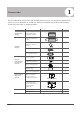
1 Accessories The air conditioning system comes with the following accessories. Use all of the installation parts and accessories to install the air conditioner. Improper installation may result in water leakage, electrical shock and fire, or equipment failure.
Safety Precautions 2 Read Safety Precautions Before Installation Incorrect installation due to ignoring instructions can cause serious damage or injury. The seriousness of potential damage or injuries is classified as either a WARNING or CAUTION. WARNING Failure to observe a warning may result in death. The appliance must be installed in accordance with national regulations. Failure to observe a caution may result in injury or equipment damage.
WARNING • The appliance shall be stored in a room without continuously operating ignition sources (for example: open flames, an operating gas appliance or an operating electric heater). • Do not pierce or burn. • The appliance shall be stored so as to prevent mechanical damage from occurring. • Be aware that the refrigerants may not contain an odour. • Compliance with national gas regulations shall be observed. • Keep ventilation openings clear of obstruction.
Note about Fluorinated Gases 1. This air-conditioning unit contains fluorinated gases. For specific information on the type of gas and the amount, please refer to the relevant label on the unit itself. 2. Installation, service, maintenance and repair of this unit must be performed by a certified technician. 3. Product uninstallation and recycling must be performed by a certified technician. 4. If the system has a leak-detection system installed, it must be checked for leaks at least every 12 months. 5.
Unit Installation Overview 3 Installation Overview INSTALLATION ORDER 1 3 2 Install the indoor unit (Page 10) 6 Install the outdoor unit (Page 14) 5 MC 4 L N MC Evacuate the refrigeration system (Page 27) 7 Perform a test run (Page 29) Page 8 Install the drainpipe (Page 17) Connect the wires (Page 24) Connect the refrigerant pipes (Page 19)
Indoor Unit Parts Installation part Louver grille Air outlet Display panel Air inlet Fig. 4.1 Safety Precautions WARNING • Securely install the indoor unit on a structure that can sustain its weight. If the structure is too weak, the unit may fall and cause personal injury, unit and property damage, or death. • DO NOT install the indoor unit in a bathroom or laundry room as excessive moisture can short the unit and corrode the wiring.
Indoor Unit Installation Instructions CAUTION DO NOT install the unit in the following locations: Areas with oil drilling or fracking Step 1: Select installation location The indoor unit should be installed in a location that meets the following requirements: Enough room exists for installation and maintenance. Enough room exists for the connecting the pipe and drainpipe. The ceiling is horizontal and its structure can sustain the weight of the indoor unit.
A Indoor Unit Installation B Refrigerant pipe connection (D. gas side) Drain point Refrigerant pipe connection (E. Liquid side) C D Hook E Fig. 4.3 Table 4.1: Indoor parts installation size MODEL(Btu/h) Length of A (mm/inch) Length of B (mm/inch) Length of C (mm/inch) Length of D (mm/inch) Length of E (mm/inch) 18K~24K 1068/42 675/26.6 235/9.3 983/38.7 220/8.7 30K~48K 1285/50.6 675/26.6 235/9.3 1200/47.2 220/8.7 36K~48K 1650/65 675/26.6 235/9.3 1565/61.6 220/8.7 1650/65 675/26.
Step 2: Hang indoor unit CAUTION Indoor Unit Installation Wood Place the square timber traversely over the roof beam, then install the hanging screw bolts. (See Fig.4.4) Timber over the beam Roof beam Ceiling Hanging screw bolts Fig. 4.4 New concrete bricks Inlaying or embedding the screw bolts. (Blade shape insertion) (Slide insertion) Fig. 4.5 Steel bar Embedding screw bolt (Pipe hanging and embedding screw bolt) Fig. 4.
Hanging arm Fig. 4.12 Grille Side board Fig. 4.10 10. Mount the indoor unit onto the hanging screw bolts with a block. Position the indoor unit on a flat level by using a level to prevent leaks. (See Fig. 4.11). D. Refrigerant pipe connection (D.gas side) E. Refrigerant pipe connection (E. Liquid side) Drain point Downward slope between(1-2)/100 Fig. 4.13 Shockproof cushion Washer Screw nut Wall Mounting Installtion Overhang part Hanging screw bolt Fig. 4.
5 Outdoor Unit Installation Outdoor Unit Installation Instructions Outdoor Unit Installation Step 1: Select installation location. The outdoor unit should be installed in the location that meets the following requirements: √ Place the outdoor unit as close to the indoor unit as possible. √ Ensure that there is enough room for installation and maintenance. √ The air inlet and outlet must not be obstructed or exposed to strong wind.
Split Type Outdoor Unit (Refer to Fig 5.4, 5.5, 5.6, 5.10 and Table 5.1) Vertical Discharge Type Outdoor Unit (Refer to Fig 5.7, 5.8, 5.9 and Table 5.2) (Wall or obstacle) Air Outlet H >120cm / 47” Fig. 5.4 Outdoor Unit Installation W W Fig. 5.7 H W H Fig. 5.5 D Fig. 5.8 A D (Wall or obstacle) B Fig. 5.6 >30cm / 11.8” Table 5.1: Length Specifications of Split Type Outdoor Unit (unit: mm/inch) Outdoor Unit Dimensions WxHxD Mounting Dimensions Distance A Air inlet >30cm / 11.
Outdoor Unit Installation 60 cm / 23.6” above NOTE: The minimum distance between the outdoor unit and walls described in the installation guide does not apply to airtight rooms. Be sure to keep the unit unobstructed in at least two of the three directions (M, N, P) (See Fig. 5.10) 30 cm / 11.8 m 0c rom ”f 1.8 /1 ck ba 3. Rotate the drain joint 90° until it clicks in place facing the front of the unit. 4.
6 Drainpipe Installation The drainpipe is used to drain water from the unit. Improper installation may cause unit and property damage. 1-1.5m (39-59”) CAUTION Downward slope 1/100 Insulate all piping to prevent condensation and water damage. • If the drainpipe is bent or installed incorrectly, water may leak and cause a malfunction of the water-level switch. • In HEAT mode, the outdoor unit will discharge water.
3. Using a 65-mm (2.5”) core drill, drill a hole in the wall. Make sure that the hole is drilled at a slight downward angle, so that the outdoor end of the hole is lower than the indoor end by about 12mm (0.5”). This will ensure proper water drainage (See Fig. 6.4). Place the protective wall cuff in the hole. This protects the edges of the hole and will help seal it when you finish the installation process. Wall Outdoor Indoor Drainpipe Installation ≈ 12mm / 0.5 inch Fig. 6.
7 Refrigerant Piping Connection Safety Precautions Notes On Pipe Length and Elevation WARNING • • • Table 7.1: The Maximum Length And Drop Height Based on Models. (Unit: m/ft.) Type of model North America, Australia and the eu frequency conversion Split Type Other Split Type Capacity (Btu/h) Length of piping Maximum drop height <15K 25/82 10/32.8 ≥15K - <24K 30/98.4 20/65.6 ≥24K - <36K 50/164 25/82 ≥36K - ≤60K 65/213 30/98.4 12K 15/49 8/26 18K-24K 25/82 15/49 30K-36K 30/98.
CAUTION • CAUTION Oil traps If the indoor unit is installed higher than the outdoor unit: -If oil flows back into the outdoor unit’s compressor, this might cause liquid compression or deterioration of oil return. Oil traps in the rising gas piping can prevent this. An oil trap should be installed every 10m (32.8ft) of vertical suction line riser. (See Fig. 7.2) If the outdoor unit is installed higher than the indoor unit: -It is recommended that vertical suction risers not be upsized.
Table 7.2 Permitted length Total piping length 18K+18K 30m/98’ 24K+24K 50m/164’ L+Max (L1, L2) 30K+30K Piping length Drop height (farthest distance from the line pipe branch) 15m/49’ L1, L2 (farthest distance from the line pipe branch) 10m/32.8’ L1-L2 Drop height between indoor and outdoor unit 20m/65.6’ H1 Drop height between two indoor units 0.5m/1.
6. Place flaring tool onto the form. 7. Turn the handle of the flaring tool clockwise until the pipe is fully flared. Flare the pipe in accordance with the dimensions shown in table 7.3. Table 7.3: PIPING EXTENSION BEYOND FLARE FORM Pipe gauge Tightening torque Flare dimension (A) (Unit: mm/Inch) Min. CAUTION Max. Ø 6.4 18-20 N.m (183-204 kgf.cm) 8.4/0.33 8.7/0.34 Ø 9.5 25-26 N.m (255-265 kgf.cm) 13.2/0.52 13.5/0.53 Ø 12.7 35-36 N.m (357-367 kgf.cm) 16.2/0.64 16.5/0.65 Ø 15.9 45-47 N.
8 Wiring Safety Precautions WARNING • • • • • • • CAUTION • • • • Connect the outdoor wires before connecting the indoor wires. Make sure you ground the unit. The grounding wire should be away from gas pipes, water pipes, lightning rods, telephone or other grounding wires. Improper grounding may cause electrical shock. DO NOT connect the unit with the power source until all wiring and piping is completed.
Table 8.2: Other Regions Rated Current of Nominal Cross-Sectional Appliance (A) Area (mm²) ≤6 0.75 6 - 10 10 - 16 16 - 25 25- 32 32 - 45 1 1.5 2.5 4 6 b. Using wire strippers, strip the rubber jacket from both ends of a signal cable to reveal about 15cm (5.9”) of the wires inside. c. Strip the insulation from the ends of the wires. d. Using a wire crimper, crimp u-lugs on the ends of the wires. NOTE: While connecting the wires, strictly follow the wiring diagram (found inside the electrical box cover). 2.
CAUTION • While connecting the wires, please strictly follow the wiring diagram. • The refrigerant circuit can become very hot. Keep the interconnection cable away from the copper tube. 5. Clamp down the cable with the designated cable clamp to secure it in place. The cable should not be loose and should not pull on the u-lugs. 6. Reattach the electric box cover. Power Specifications NOTE: Electric auxiliary heating type circuit breaker/fuse need to add more than 10 A.
Independent Power Supply Specifications MODEL(Btu/h) ≤18K 19K~24K 25K~36K 37K~48K 49K~60K PHASE 1 Phase 1 Phase 1 Phase 1 Phase 1 Phase FREQUENCY 208-240V 208-240V 208-240V 208-240V 208-240V AND VOLT CIRCUIT BREAKER/ 15/10 15/10 15/10 15/10 15/10 FUSE(A) PHASE 1 Phase 1 Phase 1 Phase 1 Phase 1 Phase POWER (outdoor) FREQUENCY 208-240V 208-240V 208-240V 208-240V 208-240V AND VOLT CIRCUIT BREAKER/ 25/20 32/25 50/40 70/55 70/60 FUSE(A) POWER (indoor) MODEL(Btu/h) ≤36K 37K~60K ≤36K 37K~60K PHASE FREQUEN
9 Air Evacuation Safety Precautions CAUTION • Use a vacuum pump with a gauge reading lower than -0.1MPa and an air discharge capacity above 40L/min. • The outdoor unit does not need vacuuming. DO NOT open the outdoor unit’s gas and liquid stop valves. • Ensure that the Compound Meter reads -0.1MPa or below after 2 hours. If after three hours of operation and the gauge reading is still above -0.1MPa, check if there is a gas leak or water inside the pipe.
Note On Adding Refrigerant CAUTION • Refrigerant charging must be performed after wiring, vacuuming, and the leak testing. • DO NOT exceed the maximum allowable quantity of refrigerant or overcharge the system. Doing so can damage the unit or impact it’s functioning. • Charging with unsuitable substances may cause explosions or accidents. Ensure that the appropriate refrigerant is used. • Refrigerant containers must be opened slowly. Always use protective gear when charging the system.
Test Run Before Test Run A test run must be performed after the entire system has been completely installed. Confirm the following points before performing the test: a) Indoor and outdoor units are properly installed. b) Piping and wiring are properly connected. c) No obstacles near the inlet and outlet of the unit that might cause poor performance or product malfunction. d) Refrigeration system does not leak. e) Drainage system is unimpeded and draining to a safe location.
European Disposal Guidelines 11 Users in European Countries may be required to properly dispose of this unit. This appliance contains refrigerant and other potentially hazardous materials. When disposing of this appliance, the law requires special collection and treatment. DO NOT dispose of this product as household waste or unsorted municipal waste. When disposing of this appliance, you have the following options: • Dispose of the appliance at designated municipal electronic waste collection facility.
Information Servicing (Required for the units adopt R32/R290 Refrigerant only) 12 1. Checks to the area Prior to beginning work on systems containing flammable refrigerants, safety checks are necessary to ensure that the risk of ignition is minimised. For repair to the refrigerating system, the following precautions shall be complied with prior to conducting work on the system. 2.
the charge size is in accordance with the room size within which the refrigerant containing parts are installed; the ventilation machinery and outlets are operating adequately and are not obstructed; if an indirect refrigerating circuit is being used, the secondary circuits shall be checked for the presence of refrigerant; marking to the equipment continues to be visible and legible.
11. Repair to intrinsically safe components Do not apply any permanent inductive or capacitance loads to the circuit without ensuring that this will not exceed the permissible voltage and current permitted for the equipment in use. Intrinscially safe components are the only types that can be worked on while live in the presence of a flammable atmosphere. The test apparatus shall be at the correct rating. Replace components only with parts specified by the manufacturer.
When the final OFN charge is used, the system shall be vented down to atmospheric pressure to enable work to take place. This operation is absolutely vital if brazing operations on the pipe-work are to take place. Ensure that the outlet for the vacuum pump is not closed to any ignition sources and there is ventilation available. 16.
18. Labelling Equipment shall be labelled stating that it has been de-commissioned and emptied of refrigerant. The label shall be dated and signed. Ensure that there are labels on the equipment stating the equipment contains flammable refrigerant. 19. Recovery When removing refrigerant from a system, either for service or decommissioning, it is recommended good practice that all refrigerants are removed safely.
The design and specifications are subject to change without prior notice for product improvement. Consult with the sales agency or manufacturer for details.