
IOM SYSHP MINI HYDRO


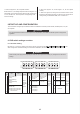
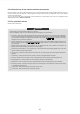
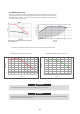
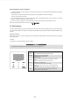
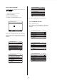
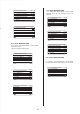
Table Of Contents

38
CN4
S1
a) Procedure
Connect the cable to the appropriate terminals as
shown in the picture.
Fix the cable reliably.
CN5
Control port signal type
Voltage
Maximum running current(A)
Wiring size(mm
2
)
Type 2
220-240VAC
0.2
0.75
Voltage
Maximum running current(A)
Wiring size(mm
2
)
220-240VAC
0.2
0.75
Room thermostat type 1(High voltage): "POWER IN" provide the
working voltage to the RT, doesn’t provide the voltage to the RT
connector directly. Port "15 L1" provide the 220V voltage to the RT
connector. Port "15 L1" connect from the unit main power supply
port L of 1- phase power supply.
Room thermostat type 2(Low voltage) : "POWER IN" provide the
working voltage to the RT
6) For room thermostat:
Method B
RT1
C
POWER
IN
H
Method A
RT1
POWER
IN
Room thermostat type 1 (High voltage):
Method C
RT1
POWER IN
RT2
POWER IN
3 15 4
�
�
����
CN11
25 26
1
2
3
4
5
6
7
8
9
10
CN7 CN30
27 28
29 30
31
32
15
3 4
�
�
����
CN11
25 26
1
2
3
4
5
6
7
8
9
10
CN7 CN30
27 28
29 30
31
32
15
3
�
�
����
CN11
25 26
1
2
3
4
5
6
7
8
9
10
CN7 CN30
27 28
29 30
31
32
15
3 4
L1
L1H
C
H
L1
There are two optional connect method depend on
the room thermostat type.
NOTE
There are three methods for connecting the thermostat cable
(as described in the picture above) and it depends on the
application.
Method A
RT can control heating and cooling individually, like the
controller for 4-pipe FCU. When the indoor unit is connected
with the external temperature controller, user interface FOR
SERVICEMAN set ROOM THERMOSTAT to MODE SET:
A.1 When unit detect voltage is 230VAC between C and L1
,the
unit operates in the cooling mode.
A.2
When unit detect voltage is 230VAC between H and L1,
the
unit operates in the heating mode.
A.3 When unit detect voltage is 0VAC for both side(C-L1,
H-L1)
the unit stop working for space heating or cooling.
A.4
When unit detect voltage is 230VAC for both
side(C-L1,
H-L1) the unit working in cooling mode.
Method B
RT provide the switch signal to unit. User interface FOR
SERVICEMAN set ROOM THERMOSTAT to ONE ZONE:
B.1 When unit detect voltage is 230VAC between H and L1,
unit
turns on.
B.2
When unit detect voltage is 0VAC between H and L1,
unit
turns off.
Method C
Indoor unit is connected with two room thermostat, while user
interface FOR SERVICEMAN set ROOM THERMOSTAT to
DOUBLE ZONE:
C.1 When unit detect voltage is 230VAC between H and
L1
,zone1
turns on.When unit detect voltage is 0VAC between
H
and L1, zone1 turns off.
C.2
When unit detect voltage is 230VAC between C and
L1,
zone2 turns on according to climate temp curve. When unit
detect voltage is 0V between C and L1, zone2 turns off.
C.3 When H-L1 and C-L1 are detected as 0VAC, unit turns off.
C.4 when H-L1 and C-L1 are detected as 230VAC, both zone1
and zone2 turn on.
zone1 zone2
(Mode set control)
(One zone control)
(Double zone control)
(Mode set control)
(One zone control)
(Double zone control)