
EDM SYSHP MINI SPLIT 06 16


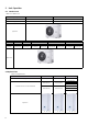


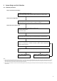
Table Of Contents
- CONTENTS
- CONTENTS
- 1.1 System Schematic
- 1.2 System Configurations
- 2 Unit Capacities
- 2.1 Outdoor unit
- 3 Nomenclature
- 3.1 Outdoor unit
- 3.2 Hydronic box
- 4 System Design and Unit Selection
- 4.1 Selection procedure
- 4.2 M thermal Leaving Water Temperature (LWT) Selection
- 5 Typical Applications
- 5.1 Space Heating Only
- 5.2 Space Heating and Domestic Hot Water
- 5.3 Space Heating, Space Cooling and Domestic Hot Water
- 5.4 Space Heating and Domestic Hot Water (Bivalent)
- 5.4.2 Auxiliary heat source provides space heating and domestic hot water
- 5.5 Space Heating Through Floor Heating Loops and Radiators
- 5.6 Space Heating, Space Cooling and Domestic Hot Water Compatible with Solar Water Heater
- Part 2 Engineering Data
- 1.1 Outdoor Unit
- 1.2 Hydronic Box
- 2 Dimensions and Center of Gravity
- 2.1 Outdoor Unit
- 2.2 Hydronic Box
- 3.1 Outdoor Unit
- 4 Wiring Diagrams
- 4.1 Outdoor Unit
- 4.2 Hydronic Box
- 5 Capactiy Tables
- 5.2 Cooling Capacity Tables (Test standard:EN14511)
- 7 Hydronic Performance
- 8.1 Overall
- 8.2 Octave Band Levels
- 9.1 Outdoor Unit
- 1.1 Notes for Installers Boxes
- 2 Installation
- 2.1 Acceptance and Unpacking
- 2.3 Outdoor unit
- 1
- 1.1
- 1.2
- 1.3
- 1.4
- 1.5
- 2.4 Hydronic box
- 3 Refrigerant Pipework
- 3.1 Permitted Piping Length and Level Difference
- 3.3 Procedure and Principles
- 3.4 Storing Copper Piping
- 3.8 Pipe Flushing
- 3.9 Gastightness Test
- 4 Water Pipework
- 4.1 Water Circuit Checks
- 4.2 Water volume and sizing expansion vessels
- 4.3 Water Circuit Connection
- 4.4 Water Circuit Anti-freeze Protection
- 5.1 General
- 5.4 Wiring Overview
- 8.1 Introduction
- 8.2 Menu Structure
- 8.11 HOLIDAY AWAY SETTING Menu
- 8.14 TEST RUN
- 8.15 SPECIAL FUNCTION
- 8.16 AUTO RESTART
- 8.20 HMI ADDRESS SET
- 9 Operation parameter
- 10 Network Configuration Guidelines
- 10.1 Install APP
- 10.2 Sign in
- 10.3 Add device and login to home Wi-Fi
- 10.4 Wired Controller Setting
- 10.4.2 Finishing up
- 11 USB Function Guidelines
- 11.1 Parameters setting transfer between wired controllers
- 11.2 Convenient program upgrade for unit
- 12 Climate Related Curves
- 13 Error Code Table
- Part 1 General Information
- Part 2 Engineering Data
- Part 3
- Installation and Field Settings
- 1 Air-to-Water HP Split System
- 2 Unit Capacities
- 3 Nomenclature
- 4 System Design and Unit Selection
- 5 Typical Applications
- 1 Specifications
- 3 Piping Diagrams
- 4 Wiring Diagrams
- 5 Capactiy Tables
- 6 Operating Limits
- 7 Hydronic Performance
- 8 Sound Levels
- 9 Accessories
- 1 Preface to Part 3
- 3 Refrigerant Pipework
- 4 Water Pipework
- 6 DIP Switch Settings
- 7 Internal Circulation Pump
- 8 User Interface Field Settings
- 9 Operation parameter
- 10 Network Configuration Guidelines
- 11 USB Function Guidelines
- 12 Climate Related Curves
- 13 Error Code Table

4
Distributor
1 Air-to-Water HP Split System
1.1 System Schemac
Figure 1-1.1: System schemac
It is an integrated air-to-water heat pump split system which is one-stop soluon for space heang, space cooling and domesc
hot water. The outdoor heat pump system extracts heat from the outdoor air and transfers this heat through refrigerant piping to
the plate heat exchanger in the hydronic box. The heated water in the hydronic box circulates to low temperature heat emiers
(under-oor heang loops or low temperature radiators) to provide space heang, and to the domesc hot water tank to provide
domesc hot water. The 4-way valve in the outdoor unit can reverse the refrigerant cycle so that the hydronic box can provide
chilled water for cooling using fan coil units.
The heang capacity of heat pumps decreases with ambient temperature dropping. Backup electric heater is customized to
provide addional heang capacity for use during extremely cold weather when the heat pump capacity is insucient.
Collector
M-Thermal Split outdoor unit
Fan Coil Units
Under-oor Heang Loops
By-pass Valve
Cold Water Inlet
DHWTank
3Way Valve
Hydronic Box