Axial Fans AW, AR Installation and Operating Instructions Document in original language | · 004 GB
© Copyright Systemair AB All rights reserved E&OE Systemair AB reserves the rights to alter their products without notice. This also applies to products already ordered, as long as it does not affect the previously agreed specifications.
Contents 1 2 3 4 5 6 7 8 9 10 11 12 13 14 15 General information .........................................1 1.1 Warning symbols ...................................1 1.1.1 Instruction symbols.....................1 Important safety information .............................1 2.1 Personnel .............................................1 2.2 Personal protective equipment..................2 2.3 5 rules of electrical safety ........................2 Warranty ..................................................
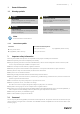
General information | 1 General information 1.1 Warning symbols Danger Caution Direct hazard Failure to comply with this warning will lead directly to death or to serious injury. Hazard with a low risk Failure to comply with this warning may lead to moderate injuries. Warning Important Potential hazard Failure to comply with this warning may lead to death or serious injury. Hazard with risk of damage to objects Failure to comply with this warning will lead to damage to objects.
2 | Warranty Table 1 Qualifications Activities Qualifications Storage, operation, transport, cleaning, disposal Trained personnel (see following note) Electrical connection, commissioning, electrical disconnection Electrical expert or matching qualification Installation, disassembly Fitter or matching qualification Maintenance Electrical expert or matching qualification Fitter or matching qualification Electrical expert or matching qualification Fitter or matching qualification Repair Smoke e
Description | Unpacking When opening the transport packaging, there is a risk of damage from sharp edges, nails, staples, splinters etc. ♦ Unpack the fan carefully. ♦ Check the fan for obvious transport damage. ♦ Only remove the packaging shortly before assembly. Transport Safety information Warning: Electrical or mechanical hazards due to fire, moisture, short circuit or malfunction. ♦ Never transport the fan by the connecting wire, terminal box, impeller, protection grille, inlet cone or silencer.
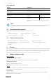
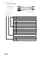
4 | Name plate and type key 6 Name plate and type key 1 Type designation 2 Voltage/frequency/current/ power/fan impeller speed 1 2 7 3 Capacity/capacitor voltage* 3 6 4 4 Moisture protection* 5 Insulation class 5 6 7 Article no.
Installation | 7 Installation Safety information General safety information General safety information ♦ Observe 2 Important safety information, page 1 ♦ Use installation material with fire resistance classes that meet temperature requirements. ♦ Provide contact and intake protection and ensure safety distances according to DIN EN ISO13857 and DIN 24167-1. ♦ To reduce transmission of vibration to the duct system, we recommend flexible connections from our accessory range, see chapter Accessories.
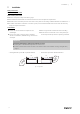
6 | Installation 7.1 Installation positions The installation is possible in any mounting position.
Electrical connection | 8 Electrical connection Safety information ♦ Observe 2 Important safety information, page 1 ♦ Prevent the ingress of water into the connection box. Connection ♦ Check if the data on the nameplate matches the connection data. ♦ Complete the electrical connection according to the circuit diagram. ♦ Connect the cable end in a dry environment. ♦ Install a circuit breaker in the permanent electrical installation, with a contact opening of at least 3 mm at each pole.
8 | Electrical connection Client side Max. speed Adjustable speed 10V –> n = max 1V –> n = min <1V –> 0 Adjustable speed through PWM 1...
Electrical connection | Table 4 Description of electrical connections of the following fans: AW 500 EC sileo (#35865), AW 500D EC (#35866), AW 560D EC sileo (#35867) Wire no. Connection Function/assignment PE PE Protective conductor 1 L1 2 L2 3 L3 1, 2* N, L* 1 NC 2 COM 3 NO Status relais, close for failure 1 OUT Analog output, 0-10 VDC, max. 3 mA, SELV output of current motor modulation level: 1 V corresponds to 10% modulation level. 10 V corresponds to 100% modulation level.
10 | Electrical connection Table 5 Description of electrical connections of the following fans: AW 630D EC sileo (#35872), AW 710D-L EC sileo (#35876), AW 800D EC sileo (#35879), AW 1000D EC sileo (#35899) Wire no.
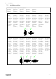
Electrical connection | 8.1 Electrical connection accessories The following wiring diagrams show the electrical connections between accessories and fans (with EC motor) or frequency converters (e.g. FRQ, FRQS, FXDM) which can be controlled with a 0–10V signal. If you are not sure if your fan is equipped with an EC- motor please see chapter 6 Name plate and type key, page 4. motor/frequency converter Wire- colours of motors with carried out cables: GND = blue MTP 10 8.2 MTP 20 +10V = red 0..
12 | Commissioning Caution Damage as a result of incorrect commissioning of the frequency converter. ♦ Install the fan and frequency converter as near as possible to one another. ♦ Use shielded cables. ♦ All components (fan, frequency converter and motor) must be grounded. ♦ We recommend using all-pole sinus filters. ♦ Avoid running the fan via the frequency converter below 10 Hz. ♦ Heating of the motor due to use of a variable frequency drive must be checked in the application by the customer.
Troubleshooting/maintenance/repair | 11.1 Troubleshooting Table 6 Troubleshooting Problem Fan does not run smoothly Air output of fan too low Grinding sounds when starting or operating the fan Thermal contacts/ resistors have triggered Fan does not reach nominal speed Motor does not rotate | 004 Possible causes Remedy Impeller imbalance Rebalancing by a specialist company if possible, otherwise contact Systemair.
14 | Troubleshooting/maintenance/repair Troubleshooting cont'd Electronics/motor overheated Insufficient cooling Improve cooling. Overloaded motor Check if the correct fan is used for your application. Ambient temperature too high Check if the correct fan is used for your application. Note: For all other damage/defects, please contact Systemair. 11.2 Maintenance Warranty claims can only be made if maintenance work is carried out correctly and written evidence thereof is provided.
Cleaning | 12 Cleaning Safety information ♦ Observe 2 Important safety information, page 1 Procedure Keeping the fan clean extends its service life. • Install a filter monitor. • Change the filters of the ventilation system. • Do not use steel brushes or sharp-edged objects. • Do not use a high-pressure cleaner (steam jet cleaner) under any circumstances. • Do not bend the fan blades when cleaning.
16 | Commissioning Report □ □ Sinus filter □ □ Shielded cables □ □ Frequency converter Yes Motor protection No Motor protection switch or motor protection relay □ □ PTC resistor □ □ Thermal contact □ □ Electrical motor protection □ □ Resistance value [Ω]: Others: Yes Functional check No Impeller easily rotatable (by hand) □ □ Rotation direction acc.
| 004
Tel.: +49 (0)7930/9272-0 Fax: +49 (0)7930/9273-92 info@systemair.de www.systemair.de Axial Fans · Installation and Operating Instructions · · en_GB · 2021-07-13 · 004 Systemair GmbH Seehöfer Str.