
OPERATION INSTRUCTIONS DANFOSS ENG

130BD531.10
U
V
W
96
97
98
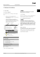
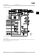
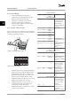
Figure 4.5 Motor Connection
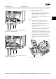
Figure 4.6, Figure 4.7, Figure 4.8 and Figure 4.9 represent line
power input, motor, and grounding for basic adjustable
frequency drives. Actual configurations vary with unit types
and optional equipment.
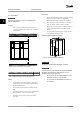
MOTOR
MOTOR
U V W
99
130BT302.12
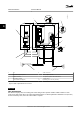
Figure 4.6 Motor Connection for Enclosure Type A2 and A3
U
V
W
96
97
98
130BT337.10
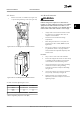
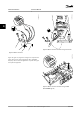
Figure 4.7 Motor Connection for Enclosure Type A4/A5
(IP55/66/NEMA Type 12)
Electrical Installation Instruction Manual
16 Danfoss A/S © Rev. 11/06/2014 All rights reserved. MG11AK22
44