
OPERATION INSTRUCTIONS DANFOSS ENG

4.8 Control Wiring
•
Isolate control wiring from high power
components in the adjustable frequency drive.
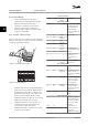
•
When the adjustable frequency drive is
connected to a thermistor, ensure that the
thermistor control wiring is shielded and
reinforced/double insulated. A 24 V DC supply
voltage is recommended.
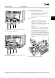
4.8.1 Control Terminal Types
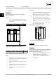
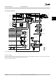
Figure 4.11 and Figure 4.12 show the removable adjustable
frequency drive connectors. Terminal functions and default
settings are summarized in Table 4.2.
2
3
4
1
130BB921.11
Figure 4.11 Control Terminal Locations
12 13 18 19 27 29 32 33 20 37
39 42 50 53 54 55
61 68 69
130BB931.10
1
2 3
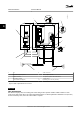
Figure 4.12 Terminal Numbers
•
Connector 1 provides four programmable digital
inputs terminals, two additional digital terminals
programmable as either input or output, a 24 V
DC terminal supply voltage, and a common for
optional customer supplied 24 V DC voltage
•
Connector 2 terminals (+) 68 and (-) 69 are for an
RS-485 serial communication connection
•
Connector 3 provides two analog inputs, one
analog output, 10 V DC supply voltage, and
commons for the inputs and output
•
Connector 4 is a USB port available for use with
the MCT 10 Set-up Software
Terminal description
Terminal Parameter Default
setting
Description
Digital Inputs/Outputs
12, 13 - +24 V DC 24 V DC supply voltage
for digital inputs and
external transducers.
Maximum output
current 200 mA for all
24 V loads.
18 5-10 [8] Start Digital inputs.
19 5-11 [0] No
operation
32 5-14 [0] No
operation
33 5-15 [0] No
operation
27 5-12 [2] Coast
inverse
For digital input or
output. Default setting
is input.
29 5-13 [14] JOG
20 - Common for digital
inputs and 0 V
potential for 24 V
supply.
37 - Safe Torque
Off (STO)
Safe input (optional).
Used for STO.
Analog Inputs/Outputs
39 - Common for analog
output.
42 6-50 Speed 0 -
High Limit
Programmable analog
output. 0–20 mA or
4–20 mA at a maximum
of 500 Ω
50 - +10 V DC 10 V DC analog supply
voltage for potenti-
ometer or thermistor.
15 mA maximum
53 6-1 Reference Analog input. For
voltage or current.
Switches A53 and A54
select mA or V.
54 6-2 Feedback
55 - Common for analog
input.
Serial Communication
61 - Integrated RC filter for
cable shield. ONLY for
connecting the shield
in the event of EMC
problems.
68 (+) 8-3 RS-485 Interface. A
control card switch is
provided for
termination resistance.
69 (-) 8-3
Electrical Installation Instruction Manual
18 Danfoss A/S © Rev. 11/06/2014 All rights reserved. MG11AK22
44