
OPERATION INSTRUCTIONS DANFOSS ENG
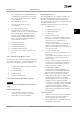

Terminal description
Terminal Parameter
Default
setting Description
Relays
01, 02, 03 5-40 [0] [9] Alarm Form C relay output.
For AC or DC voltage
and resistive or
inductive loads.
04, 05, 06 5-40 [1] [5] Running
Table 4.2 Terminal Description
Additional terminals:
•
two form C relay outputs. Location of the outputs
depends on adjustable frequency drive configu-
ration.
•
Terminals located on built-in optional equipment.
See the manual provided with the equipment
option.
4.8.2
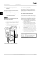
Wiring to Control Terminals
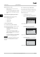
Control terminal connectors can be unplugged from the
adjustable frequency drive for ease of installation, as
shown in Figure 4.11.
NOTICE!
Keep control wires as short as possible and separate
from high power cables to minimize interference.
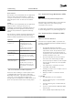
1. Open the contact by inserting a small screwdriver
into the slot above the contact and push the
screwdriver slightly upwards.
130BD546.10
2
1
10 mm
29
27
32
19
18
13
12
33
Figure 4.13 Connecting Control Wires
2. Insert the bared control wire into the contact.
3. Remove the screwdriver to fasten the control wire
into the contact.
4. Ensure the contact is firmly established and not
loose. Loose control wiring can be the source of
equipment faults or less than optimal operation.
See chapter 8.5 Cable Specifications for control terminal
wiring sizes and chapter 6 Application Set-up Examples for
typical control wiring connections.
4.8.3 Enabling Motor Operation (Terminal
27)
A jumper wire may be required between terminal 12
(or 13) and terminal 27 for the adjustable frequency drive
to operate when using factory default programming
values.
•
Digital input terminal 27 is designed to receive an
24 V DC external interlock command. In many
applications, the user wires an external interlock
device to terminal 27.
•
When no interlock device is used, wire a jumper
between control terminal 12 (recommended) or
13 to terminal 27. This provides an internal 24 V
signal on terminal 27.
•
When the status line at the bottom of the LCP
reads AUTO REMOTE COAST, this indicates that
the unit is ready to operate but is missing an
input signal on terminal 27.
•
When factory installed optional equipment is
wired to terminal 27, do not remove that wiring.
NOTICE!
The adjustable frequency drive cannot operate without a
signal on terminal 27 unless terminal 27 is re-
programmed.
Electrical Installation Instruction Manual
MG11AK22 Danfoss A/S © Rev. 11/06/2014 All rights reserved. 19
4 4