
OPERATION INSTRUCTIONS DANFOSS ENG

4.8.4 Voltage/Current Input Selection
(Switches)
The analog input terminals 53 and 54 allow setting of
input signal to voltage (0–10 V) or current (0/4–20 mA).
Default parameter settings:
•
Terminal 53: speed reference signal in open-loop
(see 16-61 Terminal 53 Switch Setting).
•
Terminal 54: feedback signal in closed-loop (see
16-63 Terminal 54 Switch Setting).
NOTICE!
Disconnect power to the adjustable frequency drive
before changing switch positions.
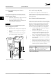
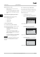
1.
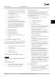
Remove the local control panel (see Figure 4.14).
2. Remove any optional equipment covering the
switches.
3. Set switches A53 and A54 to select the signal
type. U selects voltage, I selects current.
130BD530.10
1
2
N O
VLT
BUSTER.
OFF-ON
A53 A54
U- I U- I
Figure 4.14 Location of Terminals 53 and 54 Switches
4.8.5
Safe Torque Off (STO)
Safe Torque off is an option. To run Safe Torque Off,
additional wiring for the adjustable frequency drive is
required. Refer to the Safe Torque Off Instruction Manual for
further information.
4.8.6 RS-485 Serial Communication
Up to 32 nodes can be connected as a bus, or via drop
cables from a common trunk line to one network segment.
Repeaters can divide network segments. Each repeater
functions as a node within the segment in which it is
installed. Each node connected within a given network
must have a unique node address across all segments.
•
Connect RS-485 serial communication wiring to
terminals (+) 68 and (-) 69.
•
Terminate each segment at both ends, using
either the termination switch (bus term on/off,
see Figure 4.14) on the adjustable frequency
drives, or a biased termination resistor network.
•
Connect a large surface of the shield to ground,
for example with a cable clamp or a conductive
cable connector.
•
Apply potential-equalizing cables to maintain the
same ground potential throughout the network.
•
Use the same type of cable throughout the entire
network to prevent impedance mismatch.
Cable
Shielded twisted pair (STP)
Impedance
120 Ω
Max. cable
length (ft [m])
4,000 ft [1,200 m] (including drop lines)
1,650 ft [500 m] station-to-station
Table 4.3 Cable Information
Electrical Installation Instruction Manual
20 Danfoss A/S © Rev. 11/06/2014 All rights reserved. MG11AK22
44