
OPERATION INSTRUCTIONS DANFOSS ENG

WARNING 24, External fan fault
The fan warning function is an extra protective function
that checks if the fan is running/mounted. The fan warning
can be disabled in 14-53 Fan Monitor ([0] Disabled).
Troubleshooting
•
Check for proper fan operation.
•
Cycle power to the adjustable frequency drive
and check that the fan operates briefly at start-
up.
•
Check the sensors on the heatsink and control
card.
WARNING 25, Brake resistor short-circuit
The brake resistor is monitored during operation. If a short
circuit occurs, the brake function is disabled and the
warning appears. The adjustable frequency drive is still
operational but without the brake function.
Troubleshooting
•
Remove power to the adjustable frequency drive
and replace the brake resistor (see 2-15 Brake
Check).
WARNING/ALARM 26, Brake resistor power limit
The power transmitted to the brake resistor is calculated as
a mean value over the last 120 s of run time. The
calculation is based on the intermediate circuit voltage and
the brake resistance value set in 2-16 AC Brake Max.
Current. The warning is active when the dissipated braking
energy is higher than 90% of the brake resistance power. If
[2] Trip is selected in 2-13 Brake Power Monitoring, the
adjustable frequency drive trips when the dissipated
braking energy reaches 100%.
WARNING/ALARM 27, Brake chopper fault
The brake transistor is monitored during operation and if a
short circuit occurs, the brake function is disabled and a
warning is issued. The adjustable frequency drive is still
operational but, since the brake transistor has short-
circuited, substantial power is transmitted to the brake
resistor, even if it is inactive.
Troubleshooting
•
Remove power to the adjustable frequency drive
and remove the brake resistor.
WARNING/ALARM 28, Brake check failed
The brake resistor is not connected or not working.
Check 2-15 Brake Check.
ALARM 29, Heatsink temp
The maximum temperature of the heatsink has been
exceeded. The temperature fault does not reset until the
temperature falls below a defined heatsink temperature.
The trip and reset points are different based on the
adjustable frequency drive power size.
Troubleshooting
Check for the following conditions.
•
Ambient temperature too high.
•
Motor cable too long.
•
Incorrect airflow clearance above and below the
adjustable frequency drive.
•
Blocked airflow around the adjustable frequency
drive.
•
Damaged heatsink fan.
•
Dirty heatsink.
ALARM 30, Motor phase U missing
Motor phase U between the adjustable frequency drive
and the motor is missing.
Remove power from the adjustable frequency drive and
check motor phase U.
ALARM 31, Motor phase V missing
Motor phase V between the adjustable frequency drive
and the motor is missing.
Remove power from the adjustable frequency drive and
check motor phase V.
ALARM 32, Motor phase W missing
Motor phase W between the adjustable frequency drive
and the motor is missing.
Remove power from the adjustable frequency drive and
check motor phase W.
ALARM 33, Inrush fault
Too many power-ups have occurred within a short time
period. Let the unit cool to operating temperature.
WARNING/ALARM 34, Fieldbus communication fault
The serial communication bus on the communication
option card is not working.
WARNING/ALARM 36, Mains failure
This warning/alarm is only active if the supply voltage to
the adjustable frequency drive is lost and 14-10 Mains
Failure is not set to [0] No Function. Check the fuses to the
adjustable frequency drive and line power supply to the
unit.
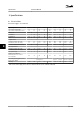
ALARM 38, Internal fault
When an internal fault occurs, a code number defined in
Table 7.4 is displayed.
Troubleshooting
•
Cycle power
•
Check that the option is properly installed
•
Check for loose or missing wiring
It may be necessary to contact your Danfoss supplier or
service department. Note the code number for further
troubleshooting directions.
Diagnostics and Troubleshoo...
Instruction Manual
MG11AK22 Danfoss A/S © Rev. 11/06/2014 All rights reserved. 41
7 7