
OPERATION INSTRUCTIONS DANFOSS ENG
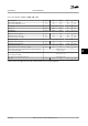
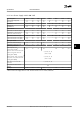
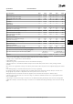

Type Designation P37K P45K P55K P75K P90K
High/Normal Load NO NO NO NO NO
Typical Shaft Output at 550 V [kW] 30 37 45 55 75
Typical Shaft Output at 690 V [kW] 37 45 55 75 90
IP20/Chassis B4 C3 C3 D3h D3h
IP21/NEMA 1 C2 C2 C2 C2 C2
IP55/NEMA 12 C2 C2 C2 C2 C2
Output current
Continuous (3 x 525–550 V) [A] 43 54 65 87 105
Intermittent (60 s overload) (3 x 525–550 V) [A] 47.3 59.4 71.5 95.7 115.5
Continuous (3 x 551–690 V) [A] 41 52 62 83 100
Intermittent (60 s overload) (3 x 551–690 V) [A] 45.1 57.2 68.2 91.3 110
Continuous kVA (550 V AC) [kVA] 41 51.4 61.9 82.9 100
Continuous kVA (690 V AC) [kVA] 49 62.1 74.1 99.2 119.5
Max. input current
Continuous (at 550 V) [A] 49 59 71 87 99
Intermittent (60 s overload) (at 550 V) [A] 53.9 64.9 78.1 95.7 108.9
Continuous (at 690 V) [A] 48 58 70 86 94.3
Intermittent (60 s overload) (at 690 V) [A] 52.8 63.8 77 94.6 112.7
Max. pre-fuses
1)
[A]
125 160 160 160 -
Additional specifications
Estimated power loss at rated max. load [W] 740 900 1100 1500 1800
Max. cable cross-section (line power and motor) [mm
2
]/(AWG)
2)
150 (300 MCM)
Max. cable cross-section (load sharing and brake) [mm
2
]/(AWG)
2)
95 (3/0)
Max. cable size with line power disconnect [mm
2
]/(AWG)
2)
95, 70, 70
(3/0, 2/0, 2/0)
185, 150, 120
(350 MCM, 300 MCM, 4/0)
Efficiency
3)
0.98 0.98 0.98 0.98 0.98
Table 8.10 Line Power Supply 3 x 525–690 V - Normal overload 110% for 1 minute, P37K-P90K
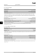
1) For type of fuse, see chapter 8.8 Fuses and Circuit Breakers.
2) American Wire Gauge.
3) Measured using 16.5 ft. [5 m] shielded motor cables at rated load and rated frequency.
4) The typical power loss is at normal load conditions and expected to be within
±
15% (tolerance relates to variety in voltage and cable
conditions).
Values are based on a typical motor efficiency. Lower efficiency motors will also add to the power loss in the adjustable frequency drive and vice
versa.
If the switching frequency is raised from nominal, the power losses may rise significantly.
LCP and typical control card power consumption values are included. Further options and customer load may add up to 30 W to the losses.
(Though typically only 4 W extra for a fully loaded control card or options for slot A or slot B, each).
Although measurements are made with state-of-the-art equipment, some measurement inaccuracy must be allowed for (
±
5%).
5) The three values for the max. cable cross-section are for single core, flexible wire and flexible wire with sleeve, respectively. Motor and line
cable: 300 MCM/150 mm
2
.
6) A2+A3 may be converted to IP21 using a conversion kit. See also Mechanical mounting and IP21/Type 1 Enclosure kit in the Design Guide.
7) B3+4 and C3+4 may be converted to IP21 using a conversion kit. See also Mechanical mounting and IP21/Type 1 Enclosure kit in the Design
Guide.
Specifications
Instruction Manual
MG11AK22 Danfoss A/S © Rev. 11/06/2014 All rights reserved. 57
8 8