
OPERATION INSTRUCTIONS DANFOSS ENG


525–600 V
Enclosure
type
Power (hp [kW]) Recommended
fuse size
Recommended
max. fuse size
Recommended circuit
breaker (Moeller)
Max. trip level [A]
A3 5.5–7.5 gG-10 (7.5 [5.5])
gG-16 (10 [7.5])
gG-32 PKZM0-25 25
B3 15–24 [11–18] gG-25 (15 [11])
gG-32 (20–25 [15–18])
gG-63 PKZM4-50 50
B4 30–50 [22–37] gG-40 (30 [22])
gG-50 (40 [30])
gG-63 (50 [37])
gG-125 NZMB1-A100 100
C3 60–75 [45–55] gG-63 (60 [45])
gG-100 (75 [55])
gG-150 NZMB2-A200 150
C4 100–125 [75–90] aR-160 (100 [75])
aR-200 (125 [90])
aR-250 NZMB2-A250 250
A5 1.5–10 [1.1–7.5] gG-10 (1.5–7.5 [1.1–5.5])
gG-16 (10 [7.5])
gG-32 PKZM0-25 25
B1 15–24 [11–18] gG-25 (15 [11])
gG-32 (20 [15])
gG-40 (25 [18.5])
gG-80 PKZM4-63 63
B2 30–40 [22–30] gG-50 (30 [22])
gG-63 (40 [30])
gG-100 NZMB1-A100 100
C1 50–75 [37–55] gG-63 (50 [37])
gG-100 (60 [45])
aR-160 (75 [55])
gG-160 (50–60 [37–45])
aR-250 (75 [55])
NZMB2-A200 160
C2 100–125 [75–90] aR-200 (100–125 [75–90]) aR-250 NZMB2-A250 250
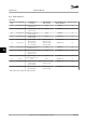
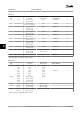
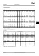
Table 8.14 525–600 V, Enclosure Types A, B and C
525–690 V
Enclosure
type
Power (hp [kW]) Recommended
fuse size
Recommended
max. fuse size
Recommended circuit
breaker (Moeller)
Max. trip level [A]
A3 1.5 [1.1]
2 [1.5]
3 [2.2]
4 [3]
5 [4]
7.5 [5.5]
10 [7.5]
gG-6
gG-6
gG-6
gG-10
gG-10
gG-16
gG-16
gG-25
gG-25
gG-25
gG-25
gG-25
gG-25
gG-25
PKZM0-16 16
B2/B4 15 [11]
20 [15]
24 [18]
30 [22]
gG-25 (15 [11])
gG-32 (20 [15])
gG-32 (24 [18])
gG-40 (30 [22])
gG-63 - -
B4/C2 40 [30] gG-63 (40 [30]) gG-80 (40 [30])
C2/C3 50 [37]
60 [45]
gG-63 (50 [37])
gG-80 (60 [45])
gG-100 (50 [37])
gG-125 (60 [45])
- -
C2 75 [55]
100 [75]
gG-100 (75 [55])
gG-125 (100 [75])
gG-160 (75–100 [55–75]) - -
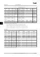
Table 8.15 525–690 V, Enclosure Types A, B and C
Specifications Instruction Manual
66 Danfoss A/S © Rev. 11/06/2014 All rights reserved. MG11AK22
88