
Operation instructions Danfoss ENG

5.
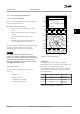
Press navigation keys to select [0] International or
[1] North America as appropriate and press [OK].
(This changes the default settings for a number
of basic parameters).
6. Press [Main Menu] on the LCP.
7. Press the navigation keys to scroll to
0-01 Language.
8. Select language and press [OK].
9. If a jumper wire is in place between control
terminals 12 and 27, leave 5-12 Terminal 27 Digital
Input at factory default. Otherwise, select No
Operation in 5-12 Terminal 27 Digital Input. For
adjustable frequency drives with an optional
bypass, no jumper wire is required between
control terminals 12 and 27.
10.
3-02 Minimum Reference
11.
3-03 Maximum Reference
12.
3-41 Ramp 1 Ramp-up Time
13.
3-42 Ramp 1 Ramp-down Time
14.
3-13 Reference Site. Linked to Hand/Auto Local
Remote.
5.4.3
Asynchronous Motor Set-up
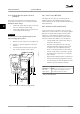
Enter the motor data in parameter 1-20 Motor Power [kW]
or 1-21 Motor Power [HP] to 1-25 Motor Nominal Speed. The
information can be found on the motor nameplate.
1.
1-20 Motor Power [kW] or 1-21 Motor Power [HP]
2.
1-22 Motor Voltage
3.
1-23 Motor Frequency
4.
1-24 Motor Current
5.
1-25 Motor Nominal Speed
5.4.4
Permanent Magnet Motor Set-up
NOTICE!
Only use permanent magnet (PM) motor with fans and
pumps.
Initial Programming Steps
1.
Activate PM motor operation 1-10 Motor
Construction, select (1) PM, non-salient SPM.
2.
Set 0-02 Motor Speed Unit to [0] RPM.
Programming motor data
After selecting PM motor in 1-10 Motor Construction, the
PM motor-related parameters in parameter groups 1-2*
Motor Data, 1-3* Addl. Motor Data and 1-4* are active.
The necessary data can be found on the motor nameplate
and in the motor data sheet.
Program the following parameters in the listed order
1.
1-24 Motor Current
2.
1-26 Motor Cont. Rated Torque
3.
1-25 Motor Nominal Speed
4.
1-39 Motor Poles
5.
1-30 Stator Resistance (Rs)
Enter line to common stator winding resistance
(R
s
). If only line-line data are available, divide the
line-line value by 2 to achieve the line to
common (starpoint) value.
It is also possible to measure the value with an
ohmmeter, which takes the resistance of the
cable into account. Divide the measured value by
2 and enter the result.
6.
1-37 d-axis Inductance (Ld)
Enter line to common direct axis inductance of
the PM motor.
If only line-line data are available, divide the line-
line value by 2 to achieve the line-common
(starpoint) value.
It is also possible to measure the value with an
inductance meter, which takes the inductance of
the cable into account. Divide the measured
value by 2 and enter the result.
7.
1-40 Back EMF at 1000 RPM
Enter line-to-line back EMF of PM Motor at
1000 RPM mechanical speed (RMS value). Back
EMF is the voltage generated by a PM motor
when no drive is connected and the shaft is
turned externally. Back EMF is normally specified
for nominal motor speed or for 1,000 RPM
measured between two lines. If the value is not
available for a motor speed of 1000 RPM,
calculate the correct value as follows: If back EMF
is, e.g., 320 V at 1800 RPM, it can be calculated at
1000 RPM as follows: Back EMF = (Voltage /
RPM)*1000 = (320/1800)*1000 = 178. This is the
value that must be programmed for 1-40 Back
EMF at 1000 RPM.
Test motor operation
1. Start the motor at low speed (100 to 200 RPM). If
the motor does not turn, check installation,
general programming and motor data.
2.
Check if start function in 1-70 PM Start Mode fits
the application requirements.
Commissioning
Instruction Manual
MG11AK22 Danfoss A/S © Rev. 11/06/2014 All rights reserved. 27
5 5