GEO 300, GEO 500 GB User Manual................................................2 Document translated from English | 278349 · v01 DE Bedienungsanleitung .................................
GB User Manual GB © Copyright Systemair UAB All rights reserved E&OE Systemair UAB reserves the rights to alter their products without notice. This also applies to products already ordered, as long as it does not affect the previously agreed specifications.
Contents 1 2 3 4 5 6 7 Introduction ...................................................5 1.1 Product description.................................5 1.2 Intended use .........................................5 1.3 Document description .............................5 1.4 Product overview ...................................5 1.5 Name plate ...........................................6 1.6 Product liability ......................................6 Safety........................................................
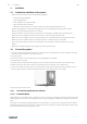
GB Introduction | 1 Introduction 1.1 Product description The product is a geothermal heat exchanger with a circulation pump and housing made of expanded polypropylene (EPP). The product is adapted for the use with ventilation unit. A geothermal heat collector absorbs the temperature of the soil and transfers the temperature to the geothermal heat exchanger. The product increases the temperature of the outdoor air during winter season to prevent damage to the ventilation unit.
GB | Safety 1.5 Name plate 1. Product name 8. IP class, enclosure class 2. Product number 9. Input power, W 3. Production year 10.Voltage, V 4. Serial number 11.Country of production 5. Maximum airflow, m³/h 12.Certifications 6. Maximum heating power, W 13.Scannable code 7. Maximum cooling power, W Use a mobile device to scan the scannable code and go to the Systemair documentation portal for more documentation and document translations. 1.
GB 2.2 Transportation and storage | Safety instructions Warning Read the warning instructions that follow before you do work on the product. • Make sure that the mains supply to the unit is disconnected before performing any maintenance or electrical work! • Read this manual and make sure that you understand the instructions before you do work on the product. • Obey local conditions and laws. • Keep this manual at the location of the product. • Do not install or operate the product if it is defective.
GB | Installation 4 Installation 4.1 To do before installation of the product • Make sure that you have the necessary installation equipment: • air duct connections (DN250) • power supply 230 VAC • tubes and siphon for condensate drain • pipes for geothermal heat collector • damper for outdoor air duct if the system is used in areas with temperatures bellow -15 °C • Examine the packaging for transportation damage and remove the packaging from the product carefully.
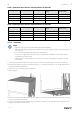
GB Installation | Table 1 Geothermal heat collector recommendations for GEO 300 Ground type Collector length (m) Pipe diameter Circulation pump stage Brine content approx. (litres) Dry sand 300 DN32 1 175 Damp sand 150 DN32 1 95 Dry loam 150 DN32 1 95 Damp loam 150 DN32 1 80 Table 2 Geothermal heat collector recommendations for GEO 500 Ground type Collector length (m) Pipe diameter Circulation pump stage Brine content approx.
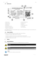
GB | Installation 7. Insulate all pipes inside the room and wall bushing to avoid condensation. 4.2.1.3 Installation sketch 4 1 2 5 3 6 1. Geothermal heat exchanger 4. Air release valve 2. Ventilation unit 5. Balance valve 3. Condensation drainage connection 6. Geothermal heat collector 4.2.2 To fill the geothermal heat collector circuit Warning • Only an authorized installer/plumber is allowed to fill the geothermal heat collector circuit.
GB Electrical connection | 8. Fill the system with the help of an external filling pump until the liquid flows out of the drain hose. 9. Close the filling valve X2. 10.Open the stopcock X0. The valve X0 is open when the handgrip is parallel to the pipe. 11.With the help of the water system's pressure, set the system under a primary pressure of 1,5 bar. Use the filling hose on filling valve X2 for that. 12.Pump the mixture through the system for about 30 minutes to remove air bubbles through the air vent.
| Commissioning 6 Commissioning 6.1 To do before the commissioning GB • Make sure that the installation and electrical connection are correctly done. • Visually examine the product and accessories for damage. • Make sure that the safety devices are correctly installed. • Make sure that there are no blockages in the air inlet and the air outlet. • Make sure that installation material and unwanted objects are removed from the product and the ducts.
GB Commissioning | • the overall length of the geothermal heat collector • the inner diameter of the geothermal heat collector • the composition of the liquid mixture • the temperature of the liquid mixture Caution Calculation and adjustment has to be done by a local installer. Adjust the pump according to the geothermal heat exchanger size to ensure ideal mode of operation. • The flow rate of the pump must be 6-7 l per minute for GEO 300.
| Operation GB Indicators of the active pump curve (I, II, III) within the control mode Note: Factory setting: Constant speed, pump curve III To go to different control mode push the control button. LEDs show the selected control mode and pump curve.
GB Maintenance | 7.2.1 To stop the product in an emergency Set the installed safety switch in the OFF position. 8 Maintenance Warning Set the installed safety switch in the OFF position before you do the maintenance unless the instructions tell you differently. Make sure that the safety switch is not accidentally set in the ON position. 8.1 Maintenance schedule The intervals are calculated from continuous operation of the product.
| Maintenance GB 6. Connect the geothermal heat exchanger and ventilation unit to the power supply. 8.3 To examine the pressure and fill the system Do a check of the system pressure on the pressure gauge. Fill the system if necessary. Caution The pressure of the hydraulic circuit has to be between 0,8 and 2,5 bar to assure an ideal operation. The optimum pressure is 1,5 bar. 1. Disconnect the geothermal heat exchanger and ventilation unit from the power supply. 2. Remove the front door. 3.
GB 8.6 Maintenance | To replace the pump 1. Disconnect the geothermal heat exchanger and ventilation unit from the power supply. 2. Remove the front door. 3. Close the stopcocks X0 and X6. 4. Connect a drain hose to the filling valve X1 to drain the liquid. 5. Open the filling valve X1 slowly until all pressure is gone. 6. Replace the pump X5. 7. Fill the system to a normal pressure of 1,5 bar. Read chapter 8.3. 8. Close the filling valve X1 and remove the filling hose. 9. Open the stopcocks X0 and X6.
GB | Troubleshooting 9. Open the stopcocks X0 and X6. 10.Put the front door back. 11.Connect the geothermal heat exchanger and ventilation unit to the power supply. 9 Troubleshooting Note: If you cannot find a solution to your problem in this section, speak to Systemair technical support. Problem Cause Solution The pump is not running. Incorrect control unit parameters. Make sure control unit settings are correct. Incorrect pump settings. Make sure the pump settings are correct.
GB 10 Disposal | Disposal The product follows the WEEE directive. This symbol on the product or the packaging of the product shows that this product is not domestic waste. The product must be recycled at an approved disposal location for electrical and electronic equipment. 10.1 To disassemble and discard the parts of the product 1. Disconnect and disassemble the product in the opposite sequence of electrical connection and installation. 2.
GB | Technical data Table 4 Heating and cooling power GEO 300 m³/h Supply air temperature (winter °C) Supply air temperature (summer °C) 100 4,26 13,5 200 1,6 16,1 300 -0,99 18,1 Table 5 Heating and cooling power GEO 500 m³/h Supply air temperature (winter °C) Supply air temperature (summer °C) 100 5,4 12,5 150 4,7 13,3 250 3,08 15 350 1,25 16,5 450 -0,35 17,8 12.
GB 13 EU Declaration of Conformity | EU Declaration of Conformity Manufacturer Systemair UAB Linų st. 101 LT–20174 Ukmergė, LITHUANIA Office: +370 340 60165 Fax: +370 340 60166 www.systemair.com The manufacturer hereby confirms that GEO 300, GEO 500 comply with all applicable requirements in the following directives and regulations.
GB | Installation report 14 Installation report Construction project: Address: Town: Type of project: Geothermal heat exchanger specification: Model: Serial No.
2783492 | v01
DE Bedienungsanleitung DE © Copyright Systemair UAB Alle Rechte vorbehalten E&OE Systemair UAB behält sich das Recht vor, ihre Produkte ohne vorherige Ankündigung zu ändern. Dies gilt auch für bereits bestellte Produkte, sofern die vorher vereinbarten Spezifikationen nicht beeinflusst werden.
Inhaltsverzeichnis 1 2 3 4 5 6 7 Einleitung .................................................... 27 1.1 Produktbeschreibung ............................ 27 1.2 Bestimmungsgemäße Verwendung ....................................... 27 1.3 Dokumentbeschreibung......................... 27 1.4 Produktübersicht .................................. 27 1.5 Typenschild......................................... 28 1.6 Produkthaftung.................................... 28 Sicherheitshinweise .......................
DE Einleitung | 1 Einleitung 1.1 Produktbeschreibung Bei dem Produkt handelt es sich um einen Erdwärmetauscher mit einer Umwälzpumpe und einem Gehäuse aus expandiertem Polypropylen (EPP). Das Produkt ist auf die Verwendung mit Lüftungsgeräten abgestimmt. Ein Erdwämekollektor absorbiert die Temperatur des Bodens und überträgt diese Temperatur an den Erdwärmetauscher. Das Produkt erhöht die Temperatur der Außenluft in den Wintermonaten, um Schäden am Lüftungsgerät zu vermeiden.
DE | Sicherheitshinweise 1.5 Typenschild 1. Produktname 8. IP-Schutzart 2. Produktnummer 9. Eingangsleistung, W 3. Fertigungsjahr 10.Spannung, V 4. Seriennummer 11.Herstellerland 5. Maximaler Luftstrom m³/h 12.Zertifizierungen 6. Maximale Heizleistung, W 13.Scannbarer Code 7. Maximale Kühlleistung, W Verwenden Sie ein Smartphone oder Tablet, um den QR-Code einzulesen und rufen Sie das Dokumentenportal von Systemair auf, um weitere Dokumente und Dokumentübersetzungen einzusehen. 1.
DE Transport und Lagerung | Hinweis! Informationen, die in einer bestimmten Situation notwendig sind. 2.2 Sicherheitsvorschriften Warnung Lesen Sie die nachfolgenden Warnhinweise, bevor Sie Arbeiten am Produkt ausführen.
DE | Installation 3.1 Packungsinhalt Falls Beschädigungen am Produkt vorliegen oder dieses unvollständig geliefert wurde, setzen Sie sich bitte unverzüglich mit dem Lieferanten in Verbindung. Der Packungsinhalt umfasst Folgendes: • Erdwärmetauscher mit integriertem G4-Filter • Wandmontagehalterung • Montageanleitung • Gummiabstandshalter (2 Stk.) 4 Installation 4.
DE Installation | 4.2.1 Installieren des Erdkollektors 4.2.1.1 Empfehlung Für 1 m³/h Luft werden ungefähr 0,5 m eines Kollektorrohrs benötigt. Bei kleineren Systemen ist jedoch ein Minimum von 100 m erforderlich. Legen Sie die Kollektorrohre auf eine Unterlage von 0,4 m Sand (je nach Typ des PE-Rohrs). Dadurch werden Schäden an den Kollektorrohren vermieden. Die Länge des Polyethylen (PE)-Rohrs hängt von den örtlichen Gegebenheiten ab, z. B. vom Bodentyp oder Grundwasserspiegel.
DE | Installation 5. Schließen Sie eine Seite des PE-Rohrs mithilfe eines Adapters am Verbindungseinlass (A), einem ¾ Zoll zugespitzten Außengewinde, des Erdwärmekollektors an. 6. Schließen Sie eine Seite des PE-Rohrs mithilfe eines Adapters am Verbindungsauslass (B), einem ¾ Zoll zugespitzten Außengewinde, des geothermalen Wärmetauschers an. 7. Isolieren Sie alle Rohre im Raum und der Wanddurchführung, um Kondensatbildung zu vermeiden. 4.2.1.3 Montagezeichnung 4 1 2 5 3 6 1. Erdwärmetauscher 4.
DE Elektrischer Anschluss | Tabelle 3 Erforderlicher prozentualer Anteil von Ethylenglykol im Gemisch Maximale Außentemperatur [ºC] Prozentualer Anteil von Ethylenglykol [%] -15 35 -20 40 -25 45 -30 50 Befüllen Sie das System wie folgt: 1. Nehmen Sie die Vordertür ab. 2. Schließen Sie mit der externen Füllpumpe einen Füllschlauch am Füllventil X1 an. 3. Schließen Sie einen Abflussschlauch am Füllventil X2 an. 4. Stecken Sie das offene Ende des Abflussschlauchs in einen Eimer. 5.
DE | Inbetriebnahme 5.3 Anschließen des Produkts am Lüftungsgerät • Vergewissern Sie sich, ob der Außentemperatursensor (OAT) im Kanal installiert ist. • Schließen Sie die Kabel des Temperatursensors (AI, GND) an einen freien analogen Eingang und an die Masse an der Anschlussbox (CB) an. • Schließen Sie die Kabel für die Steuersignale (DO, 24 V) an einen freien digitalen Ausgang und 24 V an der Anschlussbox (CB) des Lüftungsgeräts an.
DE 6.3 Inbetriebnahme | Entlüften des Systems Befüllen und entlüften Sie das System auf korrekte Weise. Gehen Sie folgendermaßen vor, wenn die Pumpe nicht automatisch entlüftet: • Drücken Sie auf die Steuertaste, halten Sie diese 3 Sekunden lang gedrückt und lassen Sie sie anschließend los. Die Pumpenentlüftungsfunktion wird gestartet und bleibt 10 Minuten lang aktiviert. Die oberen und unteren LED-Reihen blinken abwechselnd in 1-Sekunden-Intervallen.
DE | Inbetriebnahme 6.4.1 Steuermodi und -funktionen Allgemeine Anzeige LED leuchtet im Normalbetrieb grün. LED leuchtet/blinkt bei einer Störung. LED Störung Ursache Lösung Leuchtet rot Sperre Rotor ist gesperrt Motorwicklung Wicklung ist defekt Führen Sie einen manuellen Neustart aus oder kontaktieren Sie den Kundendienst.
DE Betrieb | Drücken Regelungsmodus Pumpenkurve 7 Konstanter Differenzdruck Δp-v II 8 Konstanter Differenzdruck Δp-v I 9 Konstante Drehzahl III Die Pumpe wird nach 9 Tastenbetätigungen auf die Werkseinstellungen zurückgesetzt (konstante Drehzahl, Pumpenkurve III). Manueller Neustart • Drücken Sie auf die Reglertaste und halten Sie diese 5 Sekunden lang gedrückt, um die Funktion des manuellen Neustarts aufzurufen. Die Funktion bleibt maximal 10 Minuten aktiviert.
| Wartung DE X Druck des Hydraulikkreislaufs überprüfen Reinigen des Produkts X Kondensatablauf reinigen X 8.2 Filter austauschen Hinweis! Verwenden Sie nur vom Hersteller angebotene Originalfilter. 1. Trennen Sie den Erdwärmetauscher und das Lüftungsgerät von der Stromversorgung. 2. Nehmen Sie die Vordertür ab. 3. Ziehen Sie Filter (A) oder (B) je nach Luftstromrichtung heraus. Nehmen Sie die Vordertür ab. Ziehen Sie den Filter heraus.
DE Wartung | 5. Messen Sie den prozentualen Anteil von Glykol mit einem Glykol-Refraktometer. • Befüllen Sie das System bei Bedarf mit einem gebrauchsfertigen Gemisch. Hinweis! Der prozentuale Anteil von Glykol darf nicht mehr als 3 % von der bei der Inbetriebnahme gewählten Prozentzahl abweichen. Nach dem zweimaligen Befüllen des Systems mit Wasser muss der prozentuale Anteil von Glykol angepasst werden. 6. Stellen Sie das System mithilfe des Drucks des Wassersystems auf einen Primärdruck von 1,5 bar.
DE | Fehlersuche 11.Schließen Sie den Erdwärmetauscher und das Lüftungsgerät an die Stromversorgung an. 8.7 Austauschen des Ausdehnungsgefässes 1. Trennen Sie den Erdwärmetauscher und das Lüftungsgerät von der Stromversorgung. 2. Nehmen Sie die Vordertür ab. 3. Schließen Sie die Absperrhähne X0 und X6. 4. Schließen Sie einen Schlauch am Füllventil X1 an, um die Flüssigkeit ablaufen zu lassen. 5. Öffnen Sie das Füllventil X1 langsam, bis der gesamte Druck abgelassen ist. 6.
DE Fehlersuche | Störung Ursache Lösung Die Pumpe läuft nicht. Falsche Parameter für den Regler eingestellt. Stellen Sie sicher, dass die Einstellungen für den Regler korrekt sind. Falsche Pumpeneinstellung. Stellen Sie sicher, dass die Einstellungen für die Pumpe korrekt sind. Der elektrische Anschluss wurde nicht ordnungsgemäß ausgeführt. Überprüfen Sie die Kabel und Anschlussstellen. Wenn der elektrische Anschluss korrekt ausgeführt wurde, ist die Pumpe defekt.
| Entsorgung 10 DE Entsorgung Das Produkt unterliegt den Vorgaben der WEEE Richtlinie. Dieses Symbol am Produkt oder an der Verpackung zeigt an, dass dieses Produkt nicht im Haushaltsmüll entsorgt werden darf. Das Produkt muss an einer zugelassenen Entsorgungsstelle für elektrische und elektronische Geräte recycelt werden. 10.1 Demontieren und Entsorgen von Produktteilen 1. Trennen und demontieren Sie das Produkt in zum elektrischen Anschluss und zur Installation umgekehrter Reihenfolge. 2.
DE Technische Daten | Tabelle 4 Heiz- und Kühlleistung GEO 300 m³/h Zulufttemperatur (Winter °C) Zulufttemperatur (Sommer °C) 100 4,26 13,5 200 1,6 16,1 300 -0,99 18,1 Tabelle 5 Heiz- und Kühlleistung GEO 500 m³/h Zulufttemperatur (Winter °C) Zulufttemperatur (Sommer °C) 100 5,4 12,5 150 4,7 13,3 250 3,08 15 350 1,25 16,5 450 0,35 17,8 12.
DE | EU Konformitätserklärung 13 EU Konformitätserklärung Der Hersteller Systemair UAB Linų st. 101 LT–20174 Ukmergė, LITAUEN Büro: +370 340 60165 Fax: +370 340 60166 www.systemair.de Der Hersteller bestätigt hiermit, dass GEO 300, GEO 500 alle anwendbaren Anforderungen der folgenden Richtlinien und Bestimmungen eingehalten werden.
DE 14 Montagebericht | Montagebericht Bauprojekt: Adresse: Stadt: Art des Projekts: Technische Daten des Erdwärmetauschers: Modell: Seriennr.
www.systemair.