
InstalMaintenOperInstr PP 52 DKI1

4 / 8 | PP-52_201504 | DKIR1 & DKIS1
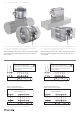
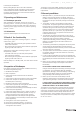
Fig. 10: Dimensions of the rectangular smoke damper with W > 1200 mm up to 1500 × 800 mm
NOTE: These smoke dampers have anges width 40 mm.
L=360
R
1
R
2
W×H
(W+80)×(H+80)
8,8×11,8
W
1
Warnings
Some damper parts can have sharp edges – therefore it
is necessary to use gloves during damper installation and
manipulation.
In order to prevent an electric injury, re or any other damage
which could result from incorrect damper usage and operation,
it is important to:
1. Install the damper in accordance with the installation manual
and by a properly trained employee.
2. Execute the damper inspection in accordance with this
installation, operation and maintenance manual.
3. Before you can install the smoke damper, it‘s functionality
must be checked according to chapter 3 Check of the
functionality.
This procedure prevents installation of a damper that has
been damaged during transportation or handling.
Do not install functionless re dampers!
Operating conditions
Smoke dampers are part of the Smoke and Heat Exhaust
Ventilation System (SHEVS). Functionality of the smoke damper
is following. In case of re damper:
• opens and removes the heat and smoke through a special fan
from the re compartment affected by re or
• closes and prevents the spread of smoke and heat in the re
compartment unaffected by re.
All smoke dampers have electric actuator as standard. They are
designed to be installed in the SHEVS ducts in locations that are
protected from weather.
Systemair smoke dampers are passive in terms of noise. There is
increased noise only when closing or opening the damper in case
of inspection or re (and it takes less than 60 seconds).
1 Installation
The installation must be done as follows:
• Duct connected to the damper must be supported or
suspended so that the damper do not bear its weight.
The damper must not bear any part of the supporting
construction. This could lead to damage and subsequent failure
of the damper.
• Actuator can be on either side of the supporting construction,
but it must be placed so that it is easy to access for inspection
and repairs.
• Distance between dampers and building structures, distribution
technology and ventilation equipment must be large enough
for reliable performance of the installation, functional testing,
inspection and repair.
• The distance between the dampers must be at least 200 mm
according to EN 1366-10.
• The distance between dampers and the wall or ceiling must be
at least 200 mm according to EN 1366-10.
• The gap between the damper and the selfstanding grill (when
installed) must be at least 200 mm according to EN 1366-10.
Otherwise the damper must be tested together with the grill.
• The smoke dampers must be installed with horizontal blade axis.
• Before the installation of the smoke damper, it‘s functionality
must be tested according to the chapter 3 Check of the
functionality.
DO NOT INSTALL NONFUNCTIONAL SMOKE DAMPERS!
• Changes of smoke damper functionality, caused by transport
or installation, aren´t reclaimable after the installation
(deformations, damages, mechanical damage of the sealing
material, foreign objects which can constrain the blade, wrong
handling of the activating mechanism etc.)
• Before connection of the smoke damper into the ductwork,
smoke damper‘s functionality must be checked again
(according to chapter 3 Check of the functionality).
IT IS NOT POSSIBLE TO CLAIM FAULTY FUNCTIONALITY CAUSED
BY PRODUCTION, TRANSPORTATION OR INSTALLATION AFTER
CONNECTING THE DUCTS TO THE SMOKE DAMPER!
During installation, it is necessary to protect the damper
mechanism and its interior against dirt. The blade must be
in the closed position. It is necessary to avoid deformation
of the damper. Installation and setup of the dampers is always
determined by SHEVS project plans that must comply with the
applicable regulations.
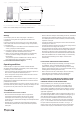
The smoke dampers DKIR1 must be installed according to Fig. 1,
the smoke dampers DKIS1 must be installed according to Fig. 2.
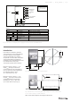
After damper installing into the SHEVS duct it is necessary
to connect electrical installation that must be done only by
authorized persons – connection has to be done according to
Fig. 3 - 7. The actuators have two microswitches indicating
the open and closed positions of the blade - see Fig. 3 - 6.
Setup, install, repair, overhaul and inspections of the dampers
must be done only by the manufacturer or by the personnel