Topvex SF02-SF12 Air Handling Unit Installation instructions Document in original language | 130324 · A006 GB
© Copyright Systemair AB All rights reserved E&OE Systemair AB reserves the rights to alter their products without notice. This also applies to products already ordered, as long as it does not affect the previously agreed specifications.
Contents 1 2 3 4 5 6 7 EU Declaration of Conformity .............................1 UK Declaration of Conformity .............................2 Warnings.......................................................3 Product information .........................................3 4.1 General ................................................3 4.2 Technical data .......................................4 4.2.1 Dimensions and weight ...............4 4.2.2 Electrical data ............................6 4.
EU Declaration of Conformity | 1 EU Declaration of Conformity Manufacturer Systemair Sverige AB Industrivägen 3 SE-739 30 Skinnskatteberg Sweden Phone: +46 222 440 00 www.systemair.com The manufacturer hereby confirms that Topvex SF comply with all applicable requirements in the following directives and regulations.
2 | UK Declaration of Conformity 2 UK Declaration of Conformity Manufacturer Systemair Sverige AB Industrivägen 3 SE-739 30 Skinnskatteberg Sweden Phone: +46 222 440 00 www.systemair.com The manufacturer hereby confirms that Topvex SF comply with all applicable requirements in the following directives and regulations.
Warnings | 3 Warnings The following admonitions will be presented in the different sections of the document: Danger • Indicates a potentially or imminently hazardous situation which, if not avoided, could result in death or serious injury. Warning • Indicates a potentially hazardous situation that may result in minor or moderate injuries. Caution • Indicates a risk of damaging the product or prevent optimal operation.
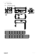
4 | Product information 4.2 4.2.1 Technical data Dimensions and weight B A I 46 F 46 E G C D H 63 E øJ ø22 W Fig.
Product information | E A I 22 H G 22 F D C K D F J 63 I B ø22 W Fig.
6 | Product information 4.2.2 Electrical data Model Fans (W tot.) 230V 1~ and 400 V 3N~ El Heating battery (kW tot.
Installation | 4.3 Transport and storage Topvex SF is delivered in one piece standing on a pallet for easy transportation using a forklift. The unit should be stored and transported in such a way that it is protected against physical damage that can harm panels, handles, display etc. It should be covered so that dust, rain and snow cannot enter and damage the unit and its components. The appliance is delivered complete with all necessary components, wrapped in plastic on a pallet for easy transportation.
8 | Installation 5.3 Installing the unit Caution Make sure that the hatch to the electrical connection box doesn’t fall down during installation in false ceiling. The unit can be installed in the positions shown in figure 3. Note: Units with electrical heating coil can not be installed with the heater downwards. When the HW units are mounted horizontally on a wall, always make sure that the water pipe connections are above the battery, so the HW battery can be properly de-aired.
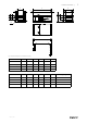
Installation | 5.3.1 Mounting brackets 30 Together with the Topvex SF unit follows 4 mounting brackets that allows the unit to be mounted according to illustration figure 3 and figure 4. A D B C Fig. 4 Model A B C D Topvex Topvex SF02EL/HW 563 523 603 1235 Topvex Topvex SF03 EL/HW 626 586 666 1322 Topvex Topvex SF04 EL/ HW 756 716 796 1322 Topvex Topvex SF06 EL/ HW 856 816 896 1322 Topvex Topvex SF08 HW 911 871 951 1322 Topvex Topvex SF12 HW 1017 977 1057 1371 5.
10 | Installation 5.4 Connection 5.4.1 Ducting Air to and from the unit is led through a duct system. To ensure long life and satisfactory cleaning possibilities, ducts made of galvanised steel are highly recommended. To obtain low energy consumption and required airflow, the duct system should be commissioned for low air speeds and low pressure drop. Fig.
Installation | 5.4.2 Electrical connection box, components Danger • Make sure that the mains power supply to the unit is disconnected before performing any maintenance or electrical work! • All electrical connections must be carried out by an authorized installer and in accordance with local rules and regulations. Caution Be careful so the hatch doesn’t fall down if the unit is false ceiling mounted. Topvex SF is equipped with a built in regulator and internal wiring.
12 | Installation 5.4.
Installation | 5.4.4 Temperature sensor, supply air and outdoor air damper Mount the enclosed duct sensor in the supply air duct. Fig. 7 Temp sensor and damper A Sensor, supply air B Motorized damper, outdoor air (accessory) The damper (accessory) is also preventing the hot water battery from freezing by closing when the returning water in the battery is below a set temperature, +8 °C, alternatively if the supply air temperature drops below a set temperature (adjustable). 5.4.
14 | Installation Table 2 From Menu overview (Operating and Maintenance Instruction) → Access rights → Log on Log on Enter password xxxx Actual level: None Log on to service level by entering a 4-digit code. After reaching the desired level go back with “LEFT” arrow (press 2 times) on the control panel. Standard code from factory to enter service level is 2222. Back to operator level: 1111. To enter Admin level code: 3333. → Inputs/Outputs AO→ ↓ AO4 Set to EAF AO4 Sign: EAF Auto Value: 0.
BMS Connection | 6 BMS Connection Communication possibilities for controller E283 WEB. • RS485(Modbus): 50-51-52 or 60-61-62 • RS485(BACnet): 50-51-52 or 60-61-62 • RS485(Exoline): 50-51-52-53 or 60-61-62-63 • TCP/IP Exoline • TCP/IP Modbus • TCP/IP WEB • TCP/IP BACnet Fig. 8 BMS connection on the controller 7 Control panel 7.1 General information The control panel is delivered connected to the Corrigo control unit situated in the electrical connection box. Cable length is 10 m.
16 | Control panel 7.2 Dimensions Fig. 9 Control panel dimensions Position Dimensions (mm) A 115.0 B 94.0 C 26.0 D c/c 60.0 E 50.
Control panel | 7.3 Installation 1. Find an appropriate place to install the control panel. Maximum length between control panel and unit is 100 m. 2. If needed, drill two holes in the wall to hang the control panel (center to center: 60 mm) (pos.1, figure 10). Fig. 10 Control panel wire connections Position 7.
130324 | A006
130324 | A006
Phone +46 222 440 00 www.systemair.