
Manual TKW

English
26 TKW
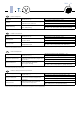
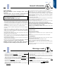
See g. 15.
• Such device is not accessible to the public. It must be installed at
least 2.5 m above ground level, unless it is installed inside engine
rooms or in similar environments.
• Install the unit as centrally as possible in the room, the air flow
direction can be controlled by manually regulating the louvres
position, according to the operating mode (cooling or heating): this
will ensure optimum distribution of the air in the room.
• During cooling mode operation the best position for the deflecting
louvres is one which allows air diffusion close to the ceiling
(Coanda effect). In heating mode, the louvres should be positioned
so that the air is directed towards the floor, in order to prevent
layers of hot air forming in the upper part of the room.
• In order to allow easy and rapid installation and maintenance,
make sure that in the selected position it is possible to remove
the ceiling panels or, if the ceiling is constructed of masonry, that
access to the unit is guaranteed.
ATTENTION:
Only restrict the air outlets as indicated in the drawing g.15
For units equipped with electric heaters the use of the"AIR SUPPLY
OBSTRUCTION" kit is NOT allowed.
Prior to installation
It is advisable to place the unit as close as possible to the installation
site before removing it from the packaging. The grille panel and the
control are separately packed for maximum protection (See g. 16).
IMPORTANT:
Do not lift the unit by the condensate drain discharge pipe; hold it
by its four corners only.
Unit installation will be facilitated using a stacker (See g. 16).
Plastic diffuser only : If plaster board ceiling panels are installed the
maximum dimensions of the unit housing must not exceed 660 x
660 mm (mod. TKW20-TKW30-TKW40) and 900 x 900 mm (mod.
TKW50-TKW60-TKW70).
In rooms with high humidity, brackets should be insulated by self
adhesive insulation supplied.
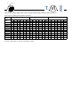
Installation
Mark the position of the hangers, connection lines and
condensate drain pipe, power supply cables and remote
control cable (see dimensions); the cardboard template
(supplied with the kit) may be of assistance for this operation.
Depending on the type of ceiling the hangers can be xed as shown
in the drawing 17.
Once the threaded hangers have been positioned, do not tighten
the nuts, and insert the washers as shown in the drawing 18.
First position the connection lines, as described in the chapter
"Water connections". Remove the "T" bar in order to facilitate
installation operations (See g. 19).
Carefully lift the unit (without the frame) using the four suspension
brackets (or the four corners), inserting it into the false ceiling.
If the "T" bar cannot be removed the unit may need to be tilted
(this operation may only be carried out with false ceilings with a
minimum height of 300 mm) (See g. 20).
Align and level the unit by adjusting the nuts and locknuts on the
threaded hangers, maintaining a distance of 25 -30 mm between
the sheet metal body and the underside of the false ceiling.
Reposition the "T" bar and align the unit in relation to the bar by
tightening the nuts and locknuts. After the condensate drain pipe
and the water ducts have been connected check, check to make
sure that the unit is level (See g. 21).
Condensate drain pipe
See g. 22 - 23.
• To ensure correct condensate water flow, the drain pipe should
have a gradient of 2% without obstructions. Furthermore an
odour trap of at least 50 mm depth should be made to prevent
unpleasant odours from reaching the room.
• Condensate may be discharged at a maximum height of 200
mm above the unit, as long as the ascending tube is vertical and
aligned with the drainage flange.
• If it is necessary to discharge the condensate from a level above
200 mm, install an auxiliary water discharge pump and float valve.
A float valve is recommended to stop the flow switch if there is a
fault at the auxiliary pump.
• The condensate pipe must be insulated with a condensation-proof
material such as polyurethane, propylene or neoprene of 5 to 10
mm thickness.
• If more than one unit is installed in the room, the drain system can
be made as shown in the drawing fig.23.
Installation