
Topvex FR Operation Diagram
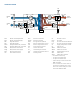

OperatiOn diagram
BAE
DEH
DO
BAS
UC
DPS
WVA
WV
ETS
HT
OT
Outdoor
Air
Exhaust
A
ir
Extract
Room Air
Supply
Room Ai
r
BFS
BFE
RM
ERW
RC
FPS
EPH WPSH
WRS
HT OT
EPRH
PRF
OS
PTE
EHS
US
DFSS
DFSE
PTS
SS
DPS
FPS
WPR
BAE
BAS
BFE
BFS
DEH*
DO*
DFSE
DFSS
DPS
2
US
4
Blower Assembly Exhaust
Blower Assembly Supply
Bag Filter Extract
Bag Filter Supply
Damper Exhaust Air, motorized
Damper Outdoor Air, motorized
Dirty Filter Sensor Extract
Dirty Filter Sensor Supply
Duct Pressure Sensor
Unit Mounted Sensor
EPH
EPRH*
ERW
EHS
ETS
FPS
HT
OT
OS*
3
RM
Electric Post-Heater
Electric Pre-Heater
Energy Recovery Wheel
Exhaust Temperature Sensor
Extract Temperature Sensor
Frost Protection Sensor
Heater Thermostat
Overheating Thermostat
Outdoor Temperature Sensor
Rotating Motor
RC
PRF*
PTE
1
PTS
1
SS
UC
WPR*
WPSH
WRS
WV*
WVA*
Rotation Control
Pre-Filter
Pressure Transmitter Exhaust
Pressure Transmitter Supply
Supply Temperature Sensor
Unit Control
Water Pre-Heater
Water Post-Heater
Wheel Rotation Sensor
Water Valve
Water Valve Actuator
* an additional accessory
1
an option for CAV Version
2
an option for VAV Version
3
comes with pre-heater accessories
EPRH and WPR
4
acts as outdoor air sensor when no
pre-heater is equiped and as extra
unit sensor in units with pre-heater
accessories EPRH ot WPR.