Topvex TR800, TR1300, TR1800, TR4000 Compact Air Handling Unit Installation Instructions Item# 415004 2022-08-11
Contents 1 Warnings......................................................................................................................................................1 2 Product Information......................................................................................................................................1 2.1 General.....................................................................................................................................................1 2.2 Technical Data....
Warnings 11Warning The following admonitions will be presented in the different sections of the document. The following admonitions will be presented in the different sections of the document.
2.2 Technical Data 2.2.1 Dimensions 4” (102mm) B 1.7 (43mm) 2.2.1.1 Dimensions Topvex TR800-1300 D A G G G F J H F E C 2.4” (62mm) Ø 4.8” (120mm) K 3.5” (88mm) H J I I F Fig. 1 Dimensions TR800-1300 in inches (mm) Table 1: Dimensions Model A B C D (c/c) E (c/c) F TR800 46.5 (1180) 48.4 (1230) 29.5 (750) 41.3 (1048) 24.3 (618) 7.6 (193) TR1300 58.3 (1480) 50.4 (1280) 33.5 (850) 53.1 (1348) 28.3 (718) 8.2 (209) Model G H I J K Ø TR800 10.4 (265) 7.
B 2.9” (73mm) 2.2.1.2 Dimensions Topvex TR1800 4” (102mm) E A I M G M H M M F 4.7” (120mm) 3.4” (87mm) KJ L K J D C 2.4” (62mm) 6.7” (171mm) Fig. 2 Dimensions TR1800 in inches (mm) Table 2: Dimensions Model A B C D E F TR1800 67.0 (1700) 50.4 (1279) 39.4 (1000) 34.2 (868) 30.9 (784) 3.9 (99) Model G H I J K L M TR1800 4.5 (114) 10.8 (274) 4.5 (114) 9.8 (250) 9.8 (250) 19.7 (500) 9.
A E B E 1.3” (33mm) 2.9” (73mm) 2.2.1.3 Dimensions Topvex TR4000 4” (102mm) D M M M M H I 2.4” (62mm) F G K L K J C 10.9” (276mm) 5.2” (132mm) 10.9” (276mm) 4.5” (114mm) 5.3” (135mm) 3.5” (90mm) Fig. 3 Dimensions TR4000 in inches (mm) Table 3: Dimensions Model A B C D E F TR4000 76.0 (1930) 78.0 (1980) 57.9 (1470) 46.5 (1180) 38.0 (965) 3.0 (76) Model G H I J K L M TR4000 4.1 (104) 5.6 (141) 4.1 (104) 4.1 (105) 9.3 (236) 39.4 (1000) 13.
2.2.2. Weights Table 4: Weight Model Weight in lbs (kg) TR800 507 (230) TR1300 639 (290) TR1800 794 (360) TR4000 1610 (730) 2.2.3 Space Required B A Fig. 4 Space required Table 5: Space required in inches (mm) Model A B TR800 26.0 (660) 22.4 (570) TR1300 30.0 (760) 28.1 (715) TR1800 35.8 (910) 32.5 (825) TR4000 54.3 (1380) 37.0 (940) Topvex TR800, TR1300, TR1800, TR4000 Installation instructions 5 Systemair Inc.
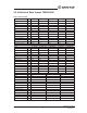
2.2.4 Electrical Data Topvex TR800-4000 Table 6: Electrical Data Model TR800-208-3 TR800EL-208-3 TR800HW-208-3 TR800-240-1 TR800HW-240-1 Voltage CA 208 208 208 240 240 Frequency Hz 60 60 60 60 60 3 3 3 1 1 Phase Current A 5.2 17.3 5.2 4.4 4.4 MCA A 5.9 20.3 5.9 5 5 MOP A 15 30 15 15 15 Total Fan Power W 1060 1060 1060 1060 1060 EL Preheater Power kW 4.5 4.5 4.5 N/A N/A EL Reheater Power kW N/A 4.5 N/A N/A N/A MCA (w/ EL Preheat) A 20.
Model TR4000-208-3 TR4000HW-208-3 Voltage CA 208 208 Frequency Hz 60 60 3 3 Phase Current A 15.4 15.4 MCA A 17.3 17.3 MOP A 25 25 Total Fan Power W 4800 4800 EL Preheater Power kW N/A N/A EL Reheater Power kW N/A N/A MCA (w/ EL Preheat) A N/A N/A MOP (w/ EL Preheat) A N/A N/A HW Preheater Capacity BTU 92800 92800 HW Reheater Capacity BTU 101300 101300 1 Warnings 2.
1 Warnings The following admonitions will be presented in the different sections of the document. 3 Installation Danger 3.1 Unpacking • Make sure that the Mains supply to the unit is disconnected before performing any maintenance or electrical work! Verify that all ordered equipment is delivered before starting the installation. Any discrepancies from the • All electrical connections must be carried out in accordance with local rules and regulations.
3.3 Ducting 3.3.1 Air Connections Principles A D B C 8 9 7 2 3 6 5 4 1 Fig. 6 Connections and basic components Table 7: Symbols and description Position Description A Connection outdoor air. B Connection supply air. C Connection extract air. D Connection exhaust air.
1 Warnings The following admonitions will be presented in the different sections of the document. 3.3.2 Condensation and Heat Insulation Danger Outdoor air duct ducts mustto always be well insulated against condensation. • Make sureand thatdischarge the Mains supply the unit is disconnected before performingCorrect any maintenance or insulation installation electrical work!on ducts connected to the unit is especially important. All ducts installed in cold rooms/areas must be well insulated.
3.4 Electric Connections All electrical connections are made in the electrical connection box which can be found in the front of the unit (Figure 7). The hatch is removed by unscrewing four screws (Figure 7). The unit must not be put into operation before all the electrical safety precautions have been read and understood. See the enclosed wiring diagram for internal and external wiring.
3.4.1 Electrical Connection Box, Components 3.4.1.1 Electrical Connection Box Components for Topvex TR800-1800 EL Topvex TR800-1800 are equipped with a built in controller and internal wiring (Figure 8). 4 5 8 3 6 2 1 13 11 10 12 9 7 Fig.
3.4.1.2 Electrical Connection Box Components for Topvex TR800-1800 HW Topvex TR800-1800 are equipped with a built in controller and internal wiring (Figure 9). 4 5 7 6 3 2 8 1 Fig.
3.4.1.3 Electrical Connection Box Components for Topvex TR4000 Topvex TR4000 are equipped with a built in controller and internal wiring (Figure 10). 5 7 4 8 6 2 3 1 Fig.
3.5 Installing the Unit The unit must be installed in the following position (Figure 6) Fig. 11 Installation position Table 11: Symbol description Symbol Description Outdoor air Supply air Extract air Exhaust air Topvex TR800, TR1300, TR1800, TR4000 Installation instructions 15 Systemair Inc.
1 Warnings 3.5.1 Installation Procedure The following admonitions will be presented in the different sections of the document. 1 Danger Prepare the surface where the unit is to be mounted. Make sure that the surface is flat, level and that it supports the weight of the unit. Perform the installation in accordance with local rules and regulations.
4 Tilt the front control panel to access the rear control panel. (TR800, TR1300 and TR1800 only) 5 Connect all the wires as indicated L3 L3 L3 L2 L2 L1 L1 L2 L1 N Fig. 12 TR 800-1800 Wire connect for 208V 3~/230V 3~ units Topvex TR800, TR1300, TR1800, TR4000 Installation instructions 17 Systemair Inc.
L2 L3 L3 L2 L2 L1 L1 L1 N Fig. 13 TR800-1800 Wire connect for 240 1~ units L3 L2 L1 Fig. 14 TR4000 Wire connect for 208V 3~/230V 3~ units Installation instructions Topvex TR800, TR1300, TR1800, TR4000 18 Systemair Inc.
3.6 Supply Air Sensor The supply air sensor is fitted in the duct 10 ft. (3 m) after the unit in the supply air duct (figure 15). Connect the sensor to terminal 30-31 (table 12) in the electrical connection box. Other temperature sensors are built in to the unit from factory. The supply air sensor is enclosed in the unit package on delivery. >3m Fig. 15 Installed supply air sensor 3.
3.
Connections to external function cont’d Unit control voltage [TB3] Main [UC] 32 32 AI2 Description Remark Sensor unit mounted Acts as outdoor air sensor when no pre-heat equipped Acts as extra unit sensor with pre-heat equipped - 33 Agnd AI reference Ground 34 34 AI4 Sensor outdoor air For units with hydronic or electric pre-heat equipped Reserved input2 35 35 AI5 Sensor CO2 (Shipped loose, mounted by others) Optional accessory3 40 40 Agnd UI analog reference 41 41 UAI1 Differe
Connections to external function cont’d Unit control voltage Description Remark DI1 Free digital (set as “Not used” from the factory) DI1 can be field configured for different applications & accessories. DI2 Free digital (set as “Not used” from the factory) [TB3] Main [UC] 71 71 72 72 Use terminal 4 for 24VDC DI2 can be field configured for different applications & accessories.
Connections to external function cont’d Unit control voltage [TB3] Expansion [PTE] 5 5 UI1 exp3 Description Remark Free universal input (set as “Not used” from the factory) UI1 exp3 can be field configured for different applications & accessories.
3.9 BMS Connection Communication possibilities for controller E283 WEB through port P1, P2 & TCP/IP • P1 (50, 51, 52, 53): BACnet MS/TP (configured by default) Modbus RS-485 • P2 (60, 61,62,63): Reserved for expansion units PTE/PTS (EXOline) BACnet MS/TP (default) OR Modbus RS-485 Expansion units (PTE/PTS) Display connection TCP/IP Fig. 17 BMS connection on the controller Installation instructions Topvex TR800, TR1300, TR1800, TR4000 24 Systemair Inc.
4 Installing the Control Panel 4.1 Dimensions A D E B C Fig. 18 Control panel dimensions Table 13: Dimensions of the control panel in inches (mm) Position Dimensions in inches (mm) A 4.5 (115.0) B 3.7 (94.0) C 1.0 (26.0) D c/c 2.4 (60.0) E 2.0 (50.5) 4.2 General Information The control panel is delivered connected to the Corrigo control unit situated in the electrical connection box. Cable length is 32 ft. (10 m).
1 2 3 5 4 7 6 Fig. 19 Control panel wire connections Table 14: Description of the control panel wire connections Position Description 1 Mounting holes 2 Connection block 3 Connection to yellow cable 4 Connection to orange cable 5 Connection to red cable 6 Connection to brown cable 7 Connection to black cable 5. Additional Equipment & Accessories For more information concerning additional external equipment such as valve actuators, motorized dampers, E-tool, roof units, wall grilles etc.
Notes Topvex TR800, TR1300, TR1800, TR4000 Installation instructions 27 Systemair Inc.
Notes Installation instructions Topvex TR800, TR1300, TR1800, TR4000 28 Systemair Inc.
Notes Topvex TR800, TR1300, TR1800, TR4000 Installation instructions 29 Systemair Inc.
Systemair Inc. reserves the right to make changes and improvements to the contents of this manual without prior notice. Systemair Inc. 50 Kanalflakt Way Bouctouche, NB E4S3M5, Canada Phone +1 519 550 3307 10048 Industrial Blvd KS, 66215 United States Phone +1 800 263 7081 service@systemair.net www.systemair.