Topvex TR800, TR1300, TR1800, TR4000 Compact Air Handling Unit Operation and Maintenance Instructions Item# 415005 2022-05-13
Contents 1 Warnings......................................................................................................................................................1 2 Product Description......................................................................................................................................1 2.1 Internal Components Topvex TR800-4000...............................................................................................1 2.2 Description of Internal Components........
Warnings 11Warning The admonitions will be in the different sectionssections of the document. Thefollowing following admonitions willpresented be presented in the different of the document.
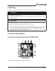
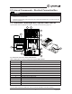
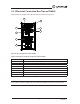
Table 1 Internal components with air connection symbols Position Description Symbols A Connection outdoor air. B Connection supply air. C Connection extract air. D Connection exhaust air. 1 Fan supply air. 2 Fan extract air 3 Filter extract air. 4 Filter outdoor air. 5 Heat exchanger. 6 Rotor motor. 7 Rotor belt 8 Re-heater electric or hydronic. 9 Pre-heater electric or water hydronic. 10 Pressure transmitter for fan & Filter guard. 11 Rotation guard for heat exchanger.
2.2 Description of Internal Components 2.2.1 Supply and Extract Air Fans The fans have external rotor motors of EC type which can be steplessly controlled individually 0 - 100%. It is possible to program the speed in 2 steps (normal/reduced) depending on the programming of the week schedule. The motor bearings are permanently lubricated and maintenance free. It is possible to remove the fans for cleaning. (Chapter 5) 2.2.1.
2.2.4 Temperature Sensors • Supply air sensor • Extract air sensor • Outdoor air sensor • Exhaust air sensor • Extra unit sensor1 1 . Only if pre heater is installed In Topvex FR800-3800 all temperature sensors are mounted and wired inside the unit except for the supply air sensor, which is delivered uninstalled with the unit and needs to be installed in the supply air duct externally from the unit. See Installation instruction for more detailed information. 2.2.
2.3 Internal Components - Electrical Connection Box Danger • Make sure that the Main power supply to the unit is disconnected before performing any maintenance or electrical work! • All electrical connections must be carried out by an authorized installer and in accordance with local rules and regulations. 2.3.1 Electrical Connection Box Topvex TR800-1800 EL Topvex TR800-1800 are equipped with a built in controller and internal wiring (Figure 3). 4 5 8 3 6 2 1 11 13 10 12 9 7 Fig.
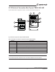
2.3.2 Electrical Connection Box Topvex TR800-1800 HW Topvex TR800-1800 are equipped with a built in controller and internal wiring (Figure 4). 4 5 7 6 8 2 3 1 Fig.
2.3.3 Electrical Connection Box Topvex TR4000 Topvex TR4000 are equipped with a built in controller and internal wiring (Figure 5). 5 7 4 8 6 2 3 1 Fig.
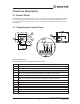
3 Interface Description 3.1 Control Panel The SCP control panel is delivered with a 32.8 Ft. (10 m) cable that is connected to the panel and with a fast coupling contact, connected to the Topvex unit. The contact is connected to the Corrigo controller in the electrical connection box (pos.1, figure 3-4-5). The cable can be unscrewed in the back of the control panel (figure 6) 3.1.1 Operating the Control Panel 1 7 2 6 8 3 4 9 5 11 10 13 12 Fig.
3.1.1.1 Navigating the menus The start display (the display normally shown) is at the root of the menu tree. Pressing DOWN will move you through the menu options. UP will move you back through the options. To enter a higher menu level, use UP or DOWN to place the cursor at the menu you wish to access and press RIGHT. If you have sufficient log on privileges the display will change to the menu you have chosen. At each level there may be several new menus which you move through using UP/DOWN.
2 Supply Air Temp Shows the supply air temperature setpoint Setp.: 64 °F 3 Time: 12.46 Press OK button to enter Time. Change time using the UP/DOWN arrow buttons. Press RIGHT to select next digit. Press OK when all digits have been entered and enter date. Date: 2010-03-12 Press OK to access the supply setpoint. Enter password 2222 by pressing OK followed by the UP/ DOWN arrow buttons. Select next digit by pressing the RIGHT arrow button. Press OK when all 4 digits have been entered.
5 Normal speed To enter Per 1 START time. Change time using the UP/DOWN arrow buttons. Press RIGHT to select next digit. Press OK to confirm and enter Per 1 STOP time. Saturday → Holiday Change time using the UP/DOWN arrow buttons. Press RIGHT to select next digit. Press OK to confirm and enter Per 2 START time. Per 1: 00:00 - 00:00 Per 2: 00:00 - 00:00 Change time using the UP/DOWN arrow buttons. Press RIGHT to select next digit. Press OK to confirm and enter Per 2 STOP time.
8 End Wizard To end Wizard press OK. Using the UP/DOWN arrow buttons to select YES. Press OK to confirm followed by the DOWN arrow button. No After finishing the setup the menu system for “Operator level” will be available. See menu overviews below that display the available menus in the Operator level followed by the “Service level” manual. To enter Service level use code 2222 in the “Access rights” menu. For operator level use code 1111.
Main menu item Sub-menu item 1 Sub-menu item 2 Explanations Free cool active: No Shows the status of the free cooling function Support control Active: No C02/VOC active Never Fire damper function Shows the status of the support control function Shows the status of the demand ventilation (C02/VOC) function Shows the status of the fire damper function Not active Operation when alarm Stopped Frost protection Shows the status of the frost protection function Active Shows the status of the cooling r
Main menu item Sub-menu item 1 Sub-menu item 2 Explanations If cascade control Shows the maximum and minimum allowed supply air temperature in case of cascade control Max/min supply setp. Outdoor temp: °F Max: 86°F Min: 53.6°F Supply air temp Actual: Shows the calculated supply air set point. The exhaust air controller output signal generates the supply air controller’s set point value 64.4°F Frost protection Actual: Shows the actual water temperature in the water heating coil.
Main menu item Sub-menu item 1 Sub-menu item 2 Explanations Outdoor comp.Setp. Set the SAF airflow compensation for the settable outdoor temperature. The outdoor compensation is linear and is set using two parameter pairs which give the value of the compensation at two different outdoor temperatures. The compensation can be positive or negative. 1 -4°C = 5.9 CFM 32°C = 0 CFM Act. CFM Comp: 0 Shows the actual airflow compensation.
Main menu item Sub-menu item 1 Sub-menu item 2 Explanations Outdoor comp.Setp. Set the SAF pressure compensation for the settable outdoor temperature. The outdoor compensation is linear and is set using two parameter pairs which give the value of the compensation at two different outdoor temperatures. The compensation can be positive or negative. 1 -4°F = 0 in.wg 50°F = 0 in.wg Act. Comp: in.wg 0 Shows the actual pressure compensation. Pressure control EAF Actual: in.wg Setp.: in.
Main menu item Sub-menu item 1 Sub-menu item 2 Explanations → Extended running Extended running Set the time for extended running. Digital inputs can be used to force the unit to start or increase to Normal running although the timer says the running mode should be Off or Reduced 60 min Time in ext. running 0 min If the running time is set to 0 the unit only runs as long as the digital input is closed. The time that extended running is active is monitored in “Time in ext.
Main menu item Sub-menu item 1 Sub-menu item 2 SAF: Auto Explanations Set the heating to Auto, Manual or Off. Manual set: 0.0 Set the manual output 0-100%. EAF: Auto Manual set: 0.0 Heating Set the heating to Auto, Manual or Off. Auto Set the manual output 0-100%. Manual set: 100.0 Exchanger Set the exchanger rotor control to Auto, Manual or Off. Auto Set the manual output 0-100%. Manual set: 0.
Main menu item Sub-menu item 1 Sub-menu item 2 Exhaust air damper → Settings Set the Exhaust air damper to Auto, Open or Close Auto → Control temp In this menu group the settings for the activated functions are available. Depending on which choices have been made in the configuration menu some of the possible alternatives may not be displayed. Supply air control Set P-band and I-time for the Supply air control function P-band: 91.4°F Note: I-time: sec 100.0 Shutdown mode P-band: 91.
Main menu item Sub-menu item 1 Sub-menu item 2 Explanations Flow control EAF Set P-band, I-time and Min. output for the Extract air fan when the unit comes configured as Flow control from factory. Alternatively Pressure control if that configuration is chosen P-band: 5885.8 CFM I-time: 10.0 sec → Alarm settings Min.
Main menu item Sub-menu item 1 Sub-menu item 2 Explanations Outd. night temp High: 59.0°F Set the upper outdoor night temperature limit for the activation of the free cooling function Low: 41°F Room temp min. 64.4°F Set the lower outdoor night temperature limit for the activation of the free cooling function Set the lower room temperature limit.
Main menu item Sub-menu item 1 Sub-menu item 2 Explanations → C02/VOC Control C02/VOC active In applications with varying occupancy the fan speeds can be controlled by the air quality as measured by C02/VOCsensor. See encl. corrigo manual (CD) for det. explanation Never Type: Fan Min. time: min 60 Set active to Never, Always or If time channel off. Set what should be regulated. Select type Fan Set the min.
→ Log off → Change password Log off No Log off from system level by changing “No” to “Yes” with the “OK” and “UP/DOWN” buttons Actual level: None Automatic logoff after 6 minutes of inactivity. Change password for Set a new password for the level of your choice. level:None Can only be done once logged on to the service level. New password xxxx 4.4 Free Cooling Description This function is used during the warm period to save energy by using cold outdoor air, e.g.
4.5 Cooling Recovery If the extract air is colder than the outdoor air and cooling is required, the heat exchanger control is reversed in order to return the cool extract air. Note The following is only valid if the cooling recovery function is set to Active in the program menu. 4.
5 Maintenance 1 Warnings 5.1 Important The following admonitions will be presented in the different sections of the document.
5.3 Maintenance Instruction 5.3.1 Changing Supply/Extract Air Filter and Pre-Filter The bag filter cannot be cleaned and must be changed when necessary. New filters can be ordered from Systemair. Operation time between filter changes depends on the air pollution at the installation site. A differential pressure switch indicates when it’s time to change the filters. This will trigger an alarm in the control panel. When this occurs do the following: 1. Replace the filters with new ones as described below 2.
5.3.2 Checking the Heat Exchanger After extended use dust may build up in the exchanger and block the air flow. It is important to clean the exchanger regularly to maintain high efficiency. The complete rotating heat exchanger block can be taken out of the unit (figure 7) in the smaller models to facilitate cleaning and maintenance. Wash in hot soapy water or use pressurized air. Do not use detergents containing ammonia. Check at least once a year that the exchanger rotor rotates easily.
5.3.4 Checking the Hot Water Heating Coil After long periods of operation (usually several years) dust may have deposited on the surface of the coil. This may reduce coil capacity. The coil can be cleaned with a pressure washer with misting jets, or with compressed air. Cleaning should be carried out carefully so as not to damage the coil’s aluminum fins. Once a year the coil water circuit needs to be vented to maintain the coil capacity 5.3.
1 Remove the cover by pressing down the locking torques at the edge of the cover using a small screwdriver, and at the same time pulling the edges outwards. 2 Grip the battery firmly with your fingers and lift it upwards until it rises from its holder. Press the new battery firmly down into place. Note that to preserve correct polarity, the battery can only be inserted the “right way round”. Topvex TR800, TR1300, TR1800, TR4000 Operation and Maintenance Instructions 29 Systemair Inc.
5.4 Troubleshooting Should problems occur, please check or correct the following before contacting your service representative. Always check if there are any alarms active in the control panel. See section 4.3 to learn how to navigate through the control panel menu. For more information on the alarm designations go to the Systemair website (www.systemair.com/na/North-America/) and download the controller user manual. 1.
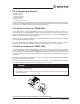
6 Service Before calling your service representative, make a note of the specification and production number from the type label (figure 9) 2 1 4 3 Fig. 9 Type label Table 7: Label description Position Description 1 Model number 2 Item number 3 Date of manufacturing (DOM) 4 Serial number Topvex TR800, TR1300, TR1800, TR4000 Operation and Maintenance Instructions 31 Systemair Inc.
Notes Operation and Maintenance Instructions Topvex TR800, TR1300, TR1800, TR4000 32 Systemair Inc.
Notes Topvex TR800, TR1300, TR1800, TR4000 Operation and Maintenance Instructions 33 Systemair Inc.
Systemair Inc. reserves the right to make changes and improvements to the contents of this manual without prior notice. Systemair Inc. 50 Kanalflakt Way Bouctouche, NB E4S3M5, Canada Phone +1 800 263 7081 10048 Industrial Blvd KS, 66215 United States Phone +1 800 263 7081 service@systemair.net www.systemair.