
415005 Topvex TR Operation and Maintenance Instructions


Topvex TR800, TR1300, TR1800, TR4000 Operation and Maintenance Instructions
Systemair Inc.
3
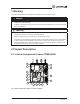
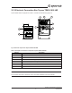
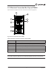
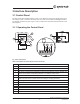
2.2 Description of Internal Components
2.2.1 Supply and Extract Air Fans
The fans have external rotor motors of EC type which can be steplessly controlled individually 0 - 100%. It
is possible to program the speed in 2 steps (normal/reduced) depending on the programming of the week
schedule. The motor bearings are permanently lubricated and maintenance free. It is possible to remove the
fans for cleaning. (Chapter 5)
2.2.1.1 Pressure Transmitter and clogged lter alarm
Two pressure transmitters maintain the airow at a constant level (CAV) by measuring the differential pressure
over the inlet cone of the fan impellers. The pressure transmitters are installed from factory in all units. An
accessory kit is available to convert the unit to a VAV in order to maintain a constant pressure in the duct. See
“VAV Installation Instructions” manual (420300) for more information.
In addition, the pressure transmitters measures the differential pressure over the supply and extract air lters.
When the pressure drop reaches the set value an alarm is triggered in the main controller. The differential
pressure can be set between 0.2 in.wg. (40Pa) and 1.2 in.wg. (300 Pa). The pressure switch is preset from
factory to 1.0 in.wg. (240 Pa).
2.2.2 Outdoor and Extract Air Filters and Pre-Filter**
The lters are of bag lter type with lter quality MERV13 for the outdoor air lter and MERV9 for the extract
air lter. The lters need to be replaced when dirty. New sets of lters can be acquired from your installer or
wholesaler.
The pre-lter(s) is of a screen type and can be cleaned by using soap water or compressed air. It can be
acquired from installer or wholesaler.
2.2.3 Heat Exchanger
Topvex TR models are equipped with a highly efcient, belt driven, rotating heat exchanger. Required supply
air temperature is therefore normally maintained without adding additional heat. The operation of the heat
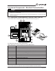
exchanger is automatic and depends on the set temperature. An extra driving belt is included on the rotor on
delivery (pos.6 gure 1).
The heat exchanger is removable for cleaning and maintenance. (Chapter 5)
2.2.3.1 Rotor Motor
The rotor motor drives the exchanger rotor with a constant rotational speed as long as there is a heat demand.
The motor is controlled by an on/off digital control signal (pos.5 gure 1).
2.2.3.2 Rotation Sensor
A sensor registers the rotation of the heat exchanger rotor. It’s connected to the main controller which gives
an alarm if the rotor stops while there is a heat demand (pos.7 gure 1).
**(only with units with pre-heater)