Topvex Series Compact Air Handling Unit HWC - Hot Water Coil EPH - Electric Pre-Heater Installation Instructions Item#: 420353 2014-06-09
Contents 1 Warnings......................................................................................................................................................1 2 Mounting of Water Heating Coil....................................................................................................................1 2.1 HW Installation in Topvex FR800-3800 (Re-Heat)....................................................................................1 2.2 HW Installation in Topvex TR800-4000 (Re-Heat).....
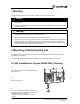
11Warning Warnings The following statements will be presented in the different sections of the document. The following admonitions will be presented in the different sections of the document.
3 1 Connect the water piping to the coil connections (pos.1 and 2). 1 Warnings The arrows in the figures display how the hot water should be connected to the coil. Connect the hot water inlet to the tube connection marked pos. 1 in the figure, and the return water to the connection The following marked pos. 2. admonitions will be presented in the different sections of the document.
6 Use the control panel to program the unit for water heating. See chapter 2.3 on how to do software configuration. 2.2 HW installation in Topvex TR800-4000 (Re-Heat) 1 Remove the cover plate by unscrewing 3 screws. 2 Insert the water heating coil as illustrated in the figure. Topvex Series 3 HWC - Hot Water Coil, ELP - Electric Pre-Heater installation instructions Systemair Inc.
3 1 Warnings Connect the water piping to the coil connections. 2 1 Cover plates around the pipeswill are be fixed to the unitin the different sections of the document. The following admonitions presented (reinforcement). The arrows in the figure display how the hot water Danger should be connected to the coil. Connect the hot water inlet to position 1 and the return water to • Make sure that the Mains supply to the unit is disconnected before performing any maintenance or position 2.
6 Use the control panel to program the unit for water heating. See chapter 2.3 on how to do software configuration. 2.3 Configuring the Software for HW (Re-heat) After all the physical installations for water heating have been done the unit software needs to be setup for water heating by the use of the control panel. This is done by activating the digital input where the frost protection sensor has been connected and set the heating option to Water. Follow procedure below.
5 Inputs/Outputs →Inputs/Outputs Go to Inputs/Outputs by using the UP/DOWN arrow buttons. Select by pressing the Right arrow button. Control function Fan control Extra Sequence Y4 6 Universal input AI Go to UI by using the UP/DOWN arrow buttons. Select by pressing the Right arrow button. DI →UI AI 7. Frost Protection UI:4 Go to UI4 by using the UP/DOWN arrow buttons. Confirm by pressing OK. Set AI sign to Not used by using the UP/DOWN arrow buttons. Confirm by pressing OK.
2.4 HW Installation in Topvex FR800-3800 (Pre-Heat) 1 Open the inspection door at the supply/extract air side of the unit. 2 Remove bag filter and frame. 3 Insert the water heating coil in front of the outdoor air connection and push the connection tubes through the prepared holes in the unit gable. 4 Re-install the bag filter and frame. Topvex Series 7 HWC - Hot Water Coil, ELP - Electric Pre-Heater installation instructions Systemair Inc.
5 1 Connect the water piping to the coil connections (pos.1 and 2). The arrows in the figures display how the hot water should be connected to the coil. Connect the hot water inlet to the tube connection marked pos. 1 in the figure, and the return water to the connection marked pos. 2. 1 Warnings The following admonitions will be presented in the different sections of the document.
8 Use the control panel to program the unit for water heating. See chapter 2.5 on how to do software configuration. 2.5 HW Installation in Topvex TR800-4000 (Pre-Heat) 1 Insert the water heating coil as illustrated in the figure. 2 Connect plug and outdoor air sensor onto existing bracket. Topvex Series 9 HWC - Hot Water Coil, ELP - Electric Pre-Heater installation instructions Systemair Inc.
3 2 Connect the water piping to the coil connections. 1 Cover plates around the pipes are fixed to the unit (reinforcement). The arrows in the figure display how the hot water should be connected to the coil. Connect the hot water inlet to position 1 and the return water to position 2. Important Take care not to damage the water coil when connecting water pipes to connectors. Connect the frost protection sensor (pos. 3) to terminals 44 and 40 in the electrical connection box.
8 Use the control panel to program the unit for water heating. See chapter 2.5 on how to do software configuration. 2.5 Configuring the Software for HW (Pre-Heat) After all the physical installations for water heating have been done the unit software needs to be setup for water heating by the use of the control panel. This is done by activating the digital input where the frost protection sensor has been connected and set the heating option to Water. Follow procedure below.
5 Inputs/Outputs →Inputs/Outputs Go to Inputs/Outputs by using the UP/DOWN buttons. Select by pressing the Right arrow button. Control function Fan control Extra Sequence Y4 6 Analog input →AI Go to AI by using the UP/DOWN arrow buttons. Select by pressing the Right arrow button. DI UI AO 7 Outdoor temp AI3: Go to AI3 by using the UP/DOWN arrow buttons. Confirm by pressing OK. Select Outdoor temp. by using the UP/DOWN buttons. Confirm by pressing OK twice. Sign: Outdoor temp.
11 Extra unit temp UI:3 Go to UI3 by using the UP/DOWN arrow buttons. Confirm by pressing OK. Set AI sign to Extra unit temp by using the UP/DOWN arrow buttons. Confirm by pressing OK. Choose AI or DI sign AI sign: Extra unit temp DI sign: Not used Set DI sign to Not used by using the UP/ DOWN arrow buttons. Confirm by pressing OK. Go back 1 step using the Left arrow button 12 Analogue outputs AO Go to AO by using the UP/DOWN arrow buttons. Select by pressing the Right arrow button.
17 Heating Fan control Go to Heating by using the UP/DOWN arrow buttons. Select by pressing the Right arrow button. Extra Sequence Y4 →Heating Exchanger 18 Water Press OK. Select Water by using the UP/DOWN arrow button. Confirm by pressing OK. Heating Water Go back 2 step by pressing the LEFT arrow button to the main menu. 17 Complete setup TOPVEX ##### Press the UP arrow button repeatedly to return to the unit status display.
3 Remove the Pre-Heater electrical box cover and connect power and control cables to the Topvex unit. 4 Replace the electrical box cover and tighten screws. 5 Use the control panel to program the unit for electric pre-heating. See chapter 3.3 on how to do software configuration. 1 Warnings The following admonitions will be presented in the different sections of the document. 3.
3 Use the control panel to program the unit for electric pre-heating. See chapter 3.3 on how to do software configuration. 3.3 Configuring the Software for EL Pre-Heater After all the physical installations for pre-heating are complete the unit software needs to be setup using the control panel. Follow procedure below. 1 Access rights Temperature Go to Access Rights by using the UP/DOWN arrow buttons. Select by pressing the Right arrow button.
5 Inputs/Outputs →Inputs/Outputs Go to Inputs/Outputs by using the UP/DOWN arrow buttons. Select by pressing the Right arrow button. Control function Fan control Extra Sequence Y4 6 Analogue input →AI Go to AI by using the UP/DOWN arrow buttons. Select by pressing the Right arrow button. DI UI AO 7 Outdoor temp AI3: Go to AI3 by using the UP/DOWN arrow buttons. Confirm by pressing OK. Select Outdoor temp by using the UP/DOWN arrow buttons. Confirm by pressing OK twice. Sign: Outdoor temp.
11 Extra unit temp UI:3 Go to UI3 by using the UP/DOWN arrow buttons. Confirm by pressing OK. Set AI sign to Extra unit temp by using the UP/DOWN arrow buttons. Confirm by pressing OK. Choose AI or DI sign AI sign: Extra unit temp DI sign: Not used Set DI sign to Not used using the UP/DOWN arrow buttons. Confirm by pressing OK. Go back 1 step using the Left arrow button 12 Analogue outputs AO Go to AO by using the UP/DOWN arrow buttons. Select by pressing the RIGHT arrow button.
16 Control mode extra Control mode extra Use the DOWN arrow button to select Control mode extra and press OK. Unit:Heating Select Heating by using the UP/DOWN arrow buttons. Confirm by pressing OK. Go back 2 steps using the left arrow button. 17 Complete setup TOPVEX ##### Press the UP arrow button repeatedly to return to the unit status display. YYYY-MM-DD HH:MM SYSTEM: STOPPED SP: ACT: ºF ↓ 3.3.1 Topvex FR Pre-Heater Electrical Components 8 2 1 7 3 8 4 5 Fig.
3.3.2 Topvex TR Pre-Heater Electrical Components Fig.
3.3.3 Topvex FR HW Pre-Heater Components 2 3 1 Fig. 4 Topvex R HW Pre-heater components Table 3: Description of HW pre-heater components Position Description 1 Filter 2 Hydronic Coil 3 Sensor Harness (Temperature sensor and Frost pevention sensor) Topvex Series 21 HWC - Hot Water Coil, ELP - Electric Pre-Heater installation instructions Systemair Inc.
3.3.4 Topvex TR HW Pre-Heater Components 1 3 2 Fig. 5 Topvex R HW Pre-heater components Table 4: Description of HW pre-heater components Position Description 1 Filter (1 pcs in TR800/1300/1800) (2 pcs TR4000) 2 Hydronic Coil 3 Sensor Harness (Temperature sensor and Frost pevention sensor) Topvex Series 22 HWC - Hot Water Coil, ELP - Electric Pre-Heater installation instructions Systemair Inc.
Notes Topvex Series 23 HWC - Hot Water Coil, ELP - Electric Pre-Heater installation instructions Systemair Inc.
Notes Topvex Series 24 HWC - Hot Water Coil, ELP - Electric Pre-Heater installation instructions Systemair Inc.
Notes Topvex Series 25 HWC - Hot Water Coil, ELP - Electric Pre-Heater installation instructions Systemair Inc.
Systemair Inc. reserves the right to make changes and improvements to the contents of this manual without prior notice. Systemair Inc. 50 Kanalflakt Way Bouctouche, NB E4S3M5, Canada Phone + 1 519 550 3307 10048 Industrial Blvd KS, 66215 United States Phone +1 517 648 2863 www.systemair.