Corrigo ventilation List of network variables for EXOline, Modbus and BACnet communication. From version 3.6.
DISCLAIMER The information in this manual has been carefully checked and is believed to be correct. Regin however, makes no warranties as regards the contents of this manual and users are requested to report errors, discrepancies or ambiguities to Regin, so that corrections may be made in future editions. The information in this document is subject to change without prior notification.
Table of contents CHAPTER 1 CORRIGO WITH EXOLINE, MODBUS AND BACNET COMMUNICATION ........................ 4 CHAPTER 2 SYSTEM INTEGRATION USING MODBUS .................................................................. 10 CHAPTER 3 COIL STATUS REGISTER ........................................................................................... 12 CHAPTER 4 INPUT REGISTER ..................................................................................................... 13 CHAPTER 5 HOLDING REGISTER.........
Chapter 1 Corrigo with EXOline, Modbus and BACnet communication Introduction Corrigo ventilation is a pre-programmed application for control of an air handling unit. The Corrigo controller can be used either stand-alone or integrated in an existing EXO project. In both cases, it is configured via the display or by using the configuration tool E tool© on a PC. This document describes all signals that are accessible via EXOline, Modbus and BACnet. It does not describe how to create an EXO project.
Baudrate 150, 300, 600, 1200, 2400, 4800, 9600 BACnet communication Corrigo is capable of communication via the BACnet-AAC (Advanced Application Controller) protocol, using either IP or MS/TP data link formats. A B-AAC unit is a device that may be intended for a specific application, but which supports some degree of programmability allows the user to do more – such as generate alarms, definine schedules, synchronize clocks, etc.
Device name CorrigoVentilation BBMD address Device ID low 2640 Device ID high 0 (x10000) Device name This is the devices name that is shown on the BAS when a device is discovered. BBMD address The BBMD address (BACnet/IP Broadcast Management Device) is used for discovering devices that are attached to different BACnet/IP subnets and separated by an IP router. The address is entered as host:port, where “host” can be the host’s name if DNS is configured.
BACnet MS/TP Configuration Upon delivery, the BACnet MS/TP protocol is disabled as a default. To enable BACnet communication, the function must first be activated.
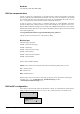
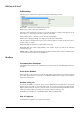
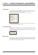
BACnet in E tool© Addressing The below picture illustrates the appearance of BACnet addressing in E tool©: BACnet/IP = Activation status of BACnet/IP protocol. BACnet device name = The name of the device. The device ID is devided into two parts, one low and one high. For example: If the high part of the ID would be “1”, then the device ID above would be “00012640”. BACnet device ID low = The lower part of the device identification.
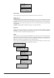
Visualised example The simplified example below visualises the Master/Slave relation. In addition to the figure, checksums for message validation are also transmitted in both query and answer.
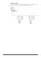
Chapter 2 System integration using Modbus Configuration The communication parameters for the Modbus line is the most important thing to configure first. As described earlier, these parameters must be identical in both the master unit and slave units, since they define the structure of messages and the transmission speed. The default configuration values of a Corrigo controller are shown in the figure below. Corrigo is set to Slave Address 1 as a default.
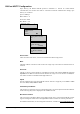
Reading values An effective way to read values is to read multiple variables simultaneously. To, for example, read all analogue outputs, set the Modbus query to the values shown in the figure below. The first analogue output variable starts at address 54 (QAnaOut.AQ1). To read address 54 to 58, set the length to 5. The Modbus answer will then communicate all 5 values in just one message, making the communication more effective.
Default value Modbus address Signal name EXOL type Chapter 3 Coil Status Register Function Description VentSettings.Cor_OverHeatFastStop L 00001 0 Settings, General Enable fast stop if overheat alarm VentSettings.Cor_CoolStepAlarmBlock L 00002 0 Settings, General Blocks cooling step signals if set and alarm "Malfunction P1 cooler" is triggered VentSettings.Cor_AlaAcknowAll L 00003 0 Settings, General Command to acknowledge all alarms VentSettings.
Signal name Default value EXOL type Modbus address Chapter 4 Input Register Function Description VentActual.Cor_Outdoor temp(0) R 30001 Actual/Setpoint Outdoor temperature (read-only) VentActual.Cor_Efficiency R 30002 Actual/Setpoint Efficiency in % for exchanger VentActual.
Default value EXOL type Modbus address Signal name Function Description VentActual.Cor_RoomTemp1 R 30010 Supply, Extract Room temperature 1 and Room temperatures VentActual.Cor_RoomTemp2 R 30011 Supply, Extract Room temperature 2 and Room temperatures VentActual. Cor_NeedRunTime I Supply, Extract Number of minutes in ongoing and Room support heating/cooling temperatures VentActual.Cor_SAFPressure R 30013 SAF/EAF Pressure and Flow Supply air fan pressure (Pa) VentActual.
Default value EXOL type Modbus address Signal name Function Description VentActual.Cor_AnalogInput6 R 30031 Universal inputs The scaled and filtered value of UAI2 VentActual.Cor_AnalogInput7 R 30032 Universal inputs The scaled and filtered value of UAI3 VentActual.Cor_AnalogInput8 R 30033 Universal inputs The scaled and filtered value of UAI4 VentSettings.
Default value EXOL type Modbus address Signal name Function Description VentSettings.Cor_UAi3 X 3040 Universal inputs Connected signal on UAI3: (See signal list for UAI1) VentSettings.Cor_UAi4 X 30041 Universal inputs Connected signal on UAI4: (See signal list for UAI1) VentSettings.
Default value EXOL type Modbus address Signal name Function Description VentSettings.Cor_UDi1 X 30050 Universal inputs Connected signal on UDI1: 0=Not used 1=SAF-Ind 2=EAF-Ind 3=P1-Heating 4=P1-Exchanger 5=P1-Cooling 6=Filter guard 7=Fire alarm 8=Fire damper-ind 9=Ext run 1/1 10=Ext run ½ 11=External alarm 12=External switch 13=Flow guard 14=Rot.sent.exch 15=De-icing 16=Frostprotection 17=Overheatprotection 18=Recirculation run 19=Change over 20=Filter guard 2 VentSettings.
Default value EXOL type Modbus address Signal name Function Description VentSettings.Cor_Ao2 X 30060 Analogue outputs Connected signal on AO2: (See signal list for AO1) VentSettings.Cor_Ao3 X 30061 Analogue outputs Connected signal on AO3: (See signal list for AO1) VentSettings.Cor_Ao4 X 30062 Analogue outputs Connected signal on AO4: (See signal list for AO1) VentSettings.Cor_Ao5 X 30063 Analogue outputs Connected signal on AO5: (See signal list for AO1) VentSettings.
Default value EXOL type Modbus address Signal name Function Description VentSettings.Cor_Do2 X 30065 Digital outputs Connected signal on DO2: (See signal list for DO1) VentSettings.Cor_Do3 X 3066 Digital outputs Connected signal on DO3: (See signal list for DO1) VentSettings.Cor_Do4 X 30067 Digital outputs Connected signal on DO4: (See signal list for DO1) VentSettings.Cor_Do5 X 30068 Digital outputs Connected signal on DO5: (See signal list for DO1) VentSettings.
Default value EXOL type Modbus address Signal name Function Description AlaData.AlaPt26_Status X 30096 Alarm Status Low efficiency AlaData.AlaPt27_Status X 30097 Alarm Status Sensor error outdoor temp AlaData.AlaPt28_Status X 30098 Alarm Status Analogue deicing AlaData.AlaPt29_Status X 30099 Alarm Status Rotation guard exchanger AlaData.AlaPt30_Status X 30100 Alarm Status Fire damper malfunction AlaData.AlaPt31_Status X 30101 Alarm Status Supply air fan control error AlaData.
Default value EXOL type Modbus address Signal name Function Description VentActual.Cor_SupplyPID_Output R 30126 Supply, Extract Supply controller output (0...100 %) and Room temperatures VentActual.Cor_ExhaustPID_Output R 30127 Supply, Extract Extract controller output (0...100 %) and Room temperatures VentActual.Cor_SAFPID_Output R 30128 SAF/EAF Pressure and Flow SAF controller output (0...100 %) VentActual.Cor_EAFPID_Output R 30129 SAF/EAF Pressure and Flow EAF controller output (0...
Default value EXOL type Modbus address Signal name Function Description VentActual.Cor_ExtSAFControl R 30151 SAF/EAF Pressure and Flow External SAF signal control (%) VentActual.Cor_ExtEAFControl R 30152 SAF/EAF Pressure and Flow External EAF signal control (%) VentActual.Cor_SAFPressure2 R 30153 SAF/EAF Pressure and Flow Pressure transmitter 2 supply air (Pa) VentActual.
Default value EXOL type Modbus address Signal name Function Description AlaData.AlaPt86_Status X 30180 Alarm Status Time for service AlaData.AlaPt87_Status X 30181 Alarm Status Y4 extra sequence control manual VentActual.Cor_ExpAnalogInput(0) R 30182 Analogue inputs The scaled and filtered value of AI1 Exp.Unit 1 VentActual.Cor_ExpAnalogInput(1) R 30183 Analogue inputs The scaled and filtered value of AI2 Exp.Unit 1 VentActual.
Default value EXOL type Modbus address Signal name Function Description VentSettings.Cor_ExpAi(0) X 30198 Analogue inputs Connected signal on AI1 Exp. Unit 1: 0=Not used 1=Outdoor temp 2=Supplytemp 3=Extracttemp 4=Roomtemp1 5=Roomtemp2 6=Exhausttemp 7=Extrasensor 8=SAF pressure 9=EAF pressure 10=Deicingtemp 11=Frost prot.temp 12=CO2 13=Humidity room 14=Humidity duct 15=Extra unit temp 16=External SAF control 17=External EAF control 18=SAF pressure 2 19=Humidity outdoor VentSettings.
Default value EXOL type Modbus address Signal name Function Description VentSettings.Cor_ExpDi(0) X 30214 Digital inputs Connected signal on DI1 Exp. Unit 1: 0=Not used 1=SAF-Ind 2=EAF-Ind 3=P1-Heating 4=P1-Exchanger 5=P1-Cooling 6=Filter guard 7=Fire alarm 8=Fire damper-ind 9=Ext run 1/1 10=Ext run ½ 11=External alarm 12=External switch 13=Flow guard 14=Rot.sent.exch 15=De-icing 16=Frostprotection 17=Overheatprotection 18=Recirculation run 19=Change over 20=Filter guard 2 VentSettings.
Default value EXOL type Modbus address Signal name Function Description VentSettings.Cor_ExpDi(12) X 30226 Digital inputs Connected signal on DI1 Exp. Unit 2: (See signal list for DI1) VentSettings.Cor_ExpDi(13) X 30227 Digital inputs Connected signal on DI2 Exp. Unit 2: (See signal list for DI1) VentSettings.Cor_ExpDi(14) X 30228 Digital inputs Connected signal on DI3 Exp. Unit 2: (See signal list for DI1) VentSettings.Cor_ExpDi(15) X 30229 Digital inputs Connected signal on DI4 Exp.
Default value EXOL type Modbus address Signal name Function Description InputOutput.Exp2AnaOut4 R 30246 Analogue outputs Value of AO4 Exp. Unit 2 InputOutput.Exp2AnaOut5 R 30247 Analogue outputs Value of AO5 Exp. Unit 2 VentSettings.Cor_ExpAo(0) X 30248 Analogue outputs Connected signal on AO1 Exp. Unit 1: 0=Not used 1=Y1-Heating 2=Y2-Exchanger 3=Y3-Cooling 4=SAF 5=EAF 6=Y6-Humidity 7=Split of Y1, Y2 or Y3 8=Extra unit 9=Heat/Cool (change over) 10=Extra sequence Y4 VentSettings.
Default value EXOL type Modbus address Signal name Function Description VentSettings.Cor_ExpDo(0) X 30258 Digital outputs Connected signal on DO1 Exp.
Default value EXOL type Modbus address Signal name Function Description VentSettings.Cor_ExpDo(3) X 30261 Digital outputs Connected signal on DO4 Exp. Unit 1: (See signal list for DO1) VentSettings.Cor_ExpDo(4) X 30262 Digital outputs Connected signal on DO5 Exp. Unit 1: (See signal list for DO1) VentSettings.Cor_ExpDo(5) X 30263 Digital outputs Connected signal on DO6 Exp. Unit 1: (See signal list for DO1) VentSettings.Cor_ExpDo(6) X 30264 Digital outputs Connected signal on DO7 Exp.
Default value EXOL type Modbus address Signal name Function Description VentActual.Cor_EAFMotorSpeedHz R 30276 SAF/EAF Pressure and Flow EAF Motor speed Hz VentActual.Cor_EAFMotorCurrent R 30277 SAF/EAF Pressure and Flow EAF Motor current A VentActual.Cor_EAFMotorPower R 30278 SAF/EAF Pressure and Flow EAF Motor Power % of nominal VentActual.Cor_EAFAccumPower R 30279 SAF/EAF Pressure and Flow EAF Accumulated Power consuption VentActual.
Default value EXOL type Modbus address Signal name Function Description VentActual.Cor_ExtraSAFAirFlow R 30293 SAF/EAF Pressure and Flow Extrasensor SAF Flow VentActual.Cor_ExtraEAFAirFlow R 30294 SAF/EAF Pressure and Flow Extrasensor EAF Flow VentActual.Cor_ExternalFlowSetP R 30295 SAF/EAF Pressure and Flow External setpoint SAF airflow (m3/h) VentActual.Cor_ExtraSeqY5 R 30296 Analogue outputs Control valve Extra sequence Y5 (0…10 V) AlaData.
Default value EXOL type Modbus address Signal name Function Description AlaData.AlaPt109_Status X 30322 Alarm Status Extra alarm 9 AlaData.AlaPt110_Status X 30323 Alarm Status Extra alarm 10 AlaData.AlaPt111_Status X 30324 Alarm Status Extra unit in manual mode AlaData.AlaPt112_Status X 30325 Alarm Status Malfunction motor control 1 AlaData.AlaPt113_Status X 30326 Alarm Status Malfunction motor control 2 AlaData.
Default value EXOL type Modbus address Signal name Function Description VentActual.Cor_ExpAnalogInput(29) R 30348 Analogue inputs The scaled and filtered value of UAI2 Exp.Unit 4 VentActual.Cor_ExpAnalogInput(30) R 30349 Analogue inputs The scaled and filtered value of Pressure A Exp.Unit 4 VentActual.Cor_ExpAnalogInput(31) R 30350 Analogue inputs The scaled and filtered value of Pressure B Exp.Unit 4 VentActual.
Default value VentSettings.Cor_Supply Setpoint R 40001 18°C Supply, Extract and Room temperatures Setpoint supply air temperature when constant supply air temperature function VentSettings.Cor_Curve1 _X1 R 40002 -20°C Supply, Extract and Room temperatures Outdoor temp for first curve point for outdoor compensated setpoint VentSettings.Cor_Curve1 _X2 R 40003 -15°C Supply, Extract and Room temperatures Outdoor temp for second curve point for outdoor compensated setpoint VentSettings.
Modbus address Default value R 40019 21°C Supply, Extract and Room temperatures Room setpoint if room temp control function VentSettings.Cor_NeedH eatStart R 40020 15°C Supply, Extract and Room temperatures Room temp for start the unit if intermittent heating control is active VentSettings.Cor_NeedH eatStop R 40021 21°C Supply, Extract and Room temperatures Room temp for stop the unit if intermittent heating control is active VentSettings.
Modbus address Default value R 40040 7 Timer Normal Speed Start time period 1 Mon. normal speed (HH.MM) TimeDp.Posts(0).T2 R 40041 16 Timer Normal Speed Stop time period 1 Mon. normal speed TimeDp.Posts(0).T3 R 40042 0 Timer Normal Speed Start time period 2 Mon. normal speed TimeDp.Posts(0).T4 R 40043 0 Timer Normal Speed Stop time period 2 Mon. normal speed TimeDp.Posts(1).T1 R 40044 7 Timer Normal Speed Start time period 1 Tue. normal speed TimeDp.Posts(1).
Modbus address Default value R 40072 0 Timer Reduced Speed Start time period 1 Mon. reduced speed (HH.MM) TimeDp.Posts(8).T2 R 40073 0 Timer Reduced Speed Stop time period 1 Mon. reduced speed TimeDp.Posts(8).T3 R 40074 0 Timer Reduced Speed Start time period 2 Mon. reduced speed TimeDp.Posts(8).T4 R 40075 0 Timer Reduced Speed Stop time period 2 Mon. reduced speed TimeDp.Posts(9).T1 R 40076 0 Timer Reduced Speed Start time period 1 Tue. reduced speed TimeDp.Posts(9).
Modbus address Default value R 40104 7 Timer Output 1 Start time period 1 Mon. timer output 1 (HH.MM) TimeDp.Posts(16).T2 R 40105 16 Timer Output 1 Stop time period 1 Mon. timer output 1 TimeDp.Posts(16).T3 R 40106 0 Timer Output 1 Start time period 2 Mon. timer output 1 TimeDp.Posts(16).T4 R 40107 0 Timer Output 1 Stop time period 2 Mon. timer output 1 TimeDp.Posts(17).T1 R 40108 7 Timer Output 1 Start time period 1 Tue. timer output 1 TimeDp.Posts(17).
Modbus address Default value R 40136 7 Timer Output 2 Start time period 1 Mon. timer output 2 (HH.MM) TimeDp.Posts(24).T2 R 40137 16 Timer Output 2 Stop time period 1 Mon. timer output 2 TimeDp.Posts(24).T3 R 40138 0 Timer Output 2 Start time period 2 Mon. timer output 2 TimeDp.Posts(24).T4 R 40139 0 Timer Output 2 Stop time period 2 Mon. timer output 2 TimeDp.Posts(25).T1 R 40140 7 Timer Output 2 Start time period 1 Tue. timer output 2 TimeDp.Posts(25).
Modbus address Default value R 40168 7 Timer Output 3 Start time period 1 Mon. timer output 3 (HH.MM) TimeDp.Posts(32).T2 R 40169 16 Timer Output 3 Stop time period 1 Mon. timer output 3 TimeDp.Posts(32).T3 R 40170 0 Timer Output 3 Start time period 2 Mon. timer output 3 TimeDp.Posts(32).T4 R 40171 0 Timer Output 3 Stop time period 2 Mon. timer output 3 TimeDp.Posts(33).T1 R 40172 7 Timer Output 3 Start time period 1 Tue. timer output 3 TimeDp.Posts(33).
Modbus address Default value R 40200 7 Timer Output 4 Start time period 1 Mon. timer output 4 (HH.MM) TimeDp.Posts(40).T2 R 40201 16 Timer Output 4 Stop time period 1 Mon. timer output 4 TimeDp.Posts(40).T3 R 40202 0 Timer Output 4 Start time period 2 Mon. timer output 4 TimeDp.Posts(40).T4 R 40203 0 Timer Output 4 Stop time period 2 Mon. timer output 4 TimeDp.Posts(41).T1 R 40204 7 Timer Output 4 Start time period 1 Tue. timer output 4 TimeDp.Posts(41).
Modbus address Default value R 40232 7 Timer Output 5 Start time period 1 Mon. timer output 5 (HH.MM) TimeDp.Posts(48).T2 R 40233 16 Timer Output 5 Stop time period 1 Mon. timer output 5 TimeDp.Posts(48).T3 R 40234 0 Timer Output 5 Start time period 2 Mon. timer output 5 TimeDp.Posts(48).T4 R 40235 0 Timer Output 5 Stop time period 2 Mon. timer output 5 TimeDp.Posts(49).T1 R 40236 7 Timer Output 5 Start time period 1 Tue. timer output 5 TimeDp.Posts(49).
Modbus address Default value R 40264 01.01 Holidays Start date holiday period 1 (MM.DD) TimeHp.Posts(0).ToDate R 40265 01.01 Holidays End date holiday period 1 (MM.DD) TimeHp.Posts(1).FromDa te R 40266 01.01 Holidays Start date holiday period 2 (MM.DD) TimeHp.Posts(1).ToDate R 40267 01.01 Holidays End date holiday period 2 (MM.DD) TimeHp.Posts(2).FromDa te R 40268 01.01 Holidays Start date holiday period 3 (MM.DD) TimeHp.Posts(2).ToDate R 40269 01.
Modbus address Default value R 40289 01.01 Holidays End date holiday period 13 (MM.DD) TimeHp.Posts(13).From Date R 40290 01.01 Holidays Start date holiday period 14 (MM.DD) TimeHp.Posts(13).ToDat e R 40291 01.01 Holidays End date holiday period 14 (MM.DD) TimeHp.Posts(14).From Date R 40292 01.01 Holidays Start date holiday period 15 (MM.DD) TimeHp.Posts(14).ToDat e R 40293 01.01 Holidays End date holiday period 15 (MM.DD) TimeHp.Posts(15).From Date R 40294 01.
Modbus address Default value R 40310 01.01 Holidays Start date holiday period 24 (MM.DD) TimeHp.Posts(23).ToDat e R 40311 01.01 Holidays End date holiday period 24 (MM.DD) VentSettings.Cor_Supply PID_PGain R 40312 33°C Settings, Control Temp P-band supply air control VentSettings.Cor_Supply PID_ITime R 40313 100 s Settings, Control Temp I-time supply air control VentSettings.Cor_Exhaus tPID_PGain R 40314 100°C Settings, Control Temp P-band extract air control VentSettings.
Modbus address Default value R 40331 300 s Settings, Control Humidity I-time humidity control VentSettings.Cor_Supply MaxDiff R 40332 10°C Settings, Alarm Limits Max control deviation supply air temp VentSettings.Cor_Supply HighAlarmLimit R 40333 30°C Settings, Alarm Limits High alarm limit supply air temp VentSettings.Cor_Supply LowAlarmLimit R 40334 10°C Settings, Alarm Limits Low alarm limit supply air temp VentSettings.
Default value Modbus address EXOL type Signal name Function Description AlaData.AlaPt32_DelayV alue I 40352 30 min Settings, Alarm Delays Alarm delay max control deviation pressure EAF AlaData.AlaPt26_DelayV alue I 40353 30 min Settings, Alarm Delays Alarm delay low efficiency AlaData.AlaPt1_DelayVa lue I 40354 120 s Settings, Alarm Delays Alarm delay malfunction SAF AlaData.AlaPt2_DelayVa lue I 40355 120 s Settings, Alarm Delays Alarm delay malfunction EAF AlaData.
Modbus address Default value X 40369 2 Manual/Auto Supply temp controller mode: 0=Manual off 1=Manual on 2=Auto VentSettings.Cor_Supply PID_ManSet R 40370 0% Manual/Auto Supply temp controller output if manual on mode VentSettings.Cor_SAFAu toMode(0) X 40371 3 Manual/Auto Running mode SAF: 0=Off 1=Manual half speed 2=Manual full speed 3=Auto VentSettings.Cor_EAFA utoMode X 40372 3 Manual/Auto Running mode EAF: 0=Off 1=Manual half speed 2=Manual full speed 3=Auto VentSettings.
Modbus address Default value R 40382 0 Manual/Auto Cooling controller output if manual mode VentSettings.Cor_Humidi tyPID_Select X 40383 2 Manual/Auto Running mode Humidification/Dehumidification: 0=Off 1=Manual 2=Auto VentSettings.Cor_Humidi tyPID_ManSet R 40384 0 Manual/Auto Humidification/Dehumidification controller output if manual mode VentSettings.Cor_HeatPu mpAutoMode(0) X 40385 2 Manual/Auto Running mode P1-Heating: 0=Manual off 1=Manual on 2=Auto VentSettings.
Modbus address Default value X 40393 4 Manual/Auto Manual/Auto Full Speed time channel: Modbus: 0=Manual-Off 1=Manual-On 2=Forced Off 3=Forced On 4=Auto BACnet: 1=Manual-Off 2=Manual-On 3=Forced Off 4=Forced On 5=Auto TimePro.TimeGroupStatu sFanHalfSpeed X 40394 4 Manual/Auto Manual/Auto Half Speed time channel: Modbus: 0=Manual-Off 1=Manual-On 2=Forced Off 3=Forced On 4=Auto BACnet: 1=Manual-Off 2=Manual-On 3=Forced Off 4=Forced On 5=Auto TimePro.
Modbus address Default value X 40399 4 Alarms.AlaAcknow X 40400 255 Alarm Acknowledging, Blocking and Unblocking External alarm acknowledge by setting this signal to the alarm number that should be acknowledge. Alarms.AlaBlock X 40401 255 Alarm Acknowledging, Blocking and Unblocking External alarm blocking by setting this signal to the alarm number that should be blocked. Alarms.
Modbus address Default value R 40416 0 SAF/EAF Pressure and Flow Pressure compensation at breakpoint 2 VentSettings.Cor_Comp2 Temp R 40417 10 SAF/EAF Pressure and Flow Outdoor temp breakpoint 2 (must be higher than breakpoint 1 temp) VentSettings.Cor_Humidi tyMaxDiff R 40418 10 % RH Humidity Max allowed difference between setpoint and humidity in room before alarm VentSettings.
Modbus address Default value R 40435 18°C Extra Unit Setpoint Extra Unit VentSettings.Cor_ExtraU nitPID1Mode X 40436 0 Extra Unit Control mode Extra Unit 0=Heating Controller 1=Cooling Controller VentSettings.Cor_ExtraU nitPID1_Select(0) X 40437 2 Manual/Auto Manual/Auto Extra Unit Controller 0=Off 1=Manual 2=Auto VentSettings.Cor_ExtraU nitPID1_ManSet(0) R 40438 0 Manual/Auto Extra Unit Controller output if manual mode VentSettings.
Modbus address Default value X 40451 2 Manual/Auto External control: Modbus: 0=Extended run full speed 1=External stop 2=No external control 3=External stop with support control BACnet: 1=Extended run full speed 2=External stop 3=No external control 4=External stop with support control VentSettings.Cor_PreHea tStart R 40452 8 Settings, PreTreatment If outdoor temp. is lower, preheat is activated VentSettings.Cor_PreCoo lStart R 40453 19 Settings, PreTreatment If outdoor temp.
Modbus address Default value R 40466 1000 CO2 Activation of demand-controlled ventilation, 1/1-speed VentSettings.Cor_Deman dCO2Diff R 40467 160 CO2 Hysteresis for stop of demand controlled ventilation (ppm) VentSettings.Cor_Cascad eTemp R 40468 13 Supply, Extract and Room temperatures Outdoor temp for switching between outdoor compensated or cascade control if Cor_VentControl = 4 or 5 (if higher outdoor temp then cascade control) VentSettings.
Modbus address Default value X 40475 0 Settings, General Select fan control mode: 0=1-Speed. 1=2-Speed. 2=Frequency control pressure 3=Frequency control air flow 4=Frequency control manually 5=Direct frequency control 6=Frequency control with slave controlled EAF 7=Frequency control with slave controlled EAF air flow depending 8=Frequency control with slave controlled SAF 9=Frequency control with slave controlled SAF air flow depending VentSettings.
Modbus address Default value R 40486 0 Settings, Free cooling SAF output when free cooling and frequency fan: 0=The output is normal speed VentSettings.Cor_NightC oolEAFOutput R 40487 0 Settings, free cooling EAF output when free cooling and frequency fan: 0=The output is normal speed AlaData.AlaPt90_DelayV alue I 40488 180 Settings, Alarm Delays VentSettings.Cor_ExtraS ensor1HighLimit(0) R 40489 30 Settings, Alarm limits Alarm limit high temp Extra sensor 1 VentSettings.
Modbus address Default value R 40507 2000 Settings, Alarm limits Alarm limit filter guard 2 X2 (m3/h) VentSettings.Cor_FilterG uard2Limit_Y2 R 40508 150 Settings, Alarm limits Alarm limit filter guard 2 Y2 (Pa) VentSettings.Cor_Neutral Zone R 40509 0 Settings, General Neutral zone around supply setpoint before heating and cooling VentSettings.Cor_ExtraU nitSaturationHumidityLi mit R 40510 85 Settings, General The Extra unit can be used in Saturation mode.
Default value Modbus address EXOL type Signal name Function Description VentSettings.Cor_FireEA R FSpeed 40526 -1 Settings, Fire mode SAF speed in fire mode 0…100 %, -1 = fan runs in normal speed conditions VentSettings.Cor_Cmp1P R ressure 40527 0 Settings, Control Pressure Pressure compensation at low point. Extra comp. curve pressure/flow setpoint. VentSettings.Cor_Cmp1 R Value 40528 15 Settings, Control Pressure Temperature for low point. Extra comp. curve pressure/flow setpoint.
Default value Signal name Modbus address EXOL type Chapter 6 Input Status Register Function Description TimePro.TimeGroupFanFullSpeed L 10001 Actual/Set Set if timechannel full speed is active point TimePro.TimeGroupFanHalfSpeed L 10002 Actual/Set Set if timechannel reduced speed is point active TimePro.TimeGroupCor_ExtraTimeG L roup1 10003 Actual/Set Set if timer output 1 is active point TimePro.
Default value Modbus address EXOL type Signal name Function Description QDig.DI3 L 10016 Digital inputs Value of DI3 QDig.DI4 L 10017 Digital inputs Value of DI4 QDig.DI5 L 10018 Digital inputs Value of DI5 QDig.DI6 L 10019 Digital inputs Value of DI6 QDig.DI7 L 10020 Digital inputs Value of DI7 QDig.DI8 L 10021 Digital inputs Value of DI8 QDig.DI9 L 10022 Universal inputs Value of UDI1 QDig.DI10 L 10023 Universal inputs Value of UDI2 QDig.
Default value Modbus address EXOL type Signal name Function Description VentActual.Cor_AlaPt(5) L 10037 Alarm Points P1 exchanger malfunction VentActual.Cor_AlaPt(6) L 10038 Alarm Points Filter guard 1 VentActual.Cor_AlaPt(7) L 10039 Alarm Points Flow guard VentActual.Cor_AlaPt(8) L 10040 Alarm Points External frost guard VentActual.Cor_AlaPt(9) L 10041 Alarm Points Deicing pressure guard VentActual.Cor_AlaPt(10) L 10042 Alarm Points Fire alarm VentActual.
Default value Modbus address EXOL type Signal name Function Description VentActual.Cor_AlaPt(26) L 10058 Alarm Points Low efficiency VentActual.Cor_AlaPt(27) L 10059 Alarm Points Sensor error outdoor temp VentActual.Cor_AlaPt(28) L 10060 Alarm Points Analogue deicing VentActual.Cor_AlaPt(29) L 10061 Alarm Points Rotation guard exchanger VentActual.Cor_AlaPt(30) L 10062 Alarm Points Fire damper malfunction VentActual.
Default value Modbus address EXOL type Signal name Function Description VentActual.Cor_AlaPt(47) L 10079 Alarm Points Manual fire damper VentActual.Cor_AlaPt(48) L 10080 Alarm Points Internal battery error VentActual.Cor_SAFStart1(0) L 10081 SAF/EAF Start signal full speed supply air fan Pressure and Flow VentActual.Cor_EAFStart1 L 10082 SAF/EAF Start signal full speed extract air fan Pressure and Flow VentActual.
Default value Modbus address EXOL type Signal name Function Description VentActual.Cor_AlaPt(57) L 10098 Alarm Points Sensor error deicing temp. VentActual.Cor_AlaPt(58) L 10099 Alarm Points Sensor error frost protection temp. VentActual.Cor_AlaPt(59) L 10100 Alarm Points Sensor error CO2 VentActual.Cor_AlaPt(60) L 10101 Alarm Points Sensor error humidity room VentActual.Cor_AlaPt(61) L 10102 Alarm Points Sensor error humidity duct VentActual.
Default value Modbus address EXOL type Signal name Function Description VentActual.Cor_AlaPt(78) L 10119 Alarm Points Alarm frequency converter EAF VentActual.Cor_AlaPt(79) L 10120 Alarm Points Communication error frequency SAF VentActual.Cor_AlaPt(80) L 10121 Alarm Points Communication error frequency EAF VentActual.Cor_AlaPt(81) L 10122 Alarm Points Communication error expansion unit 1 VentActual.
Default value Modbus address EXOL type Signal name Function Description VentActual.Cor_AlaPt(99) L 10140 Alarm Points High temp extra sensor 5 VentActual.Cor_AlaPt(100) L 10141 Alarm Points Low temp extra sensor 5 VentActual.Cor_DIReserved(14) L 10142 Alarm Points Not used VentActual.Cor_DIReserved(15) L 10143 Alarm Points Not used VentActual.Cor_DIReserved(16) L 10144 Alarm Points Not used InputOutput.
Default value Modbus address EXOL type Signal name Function Description InputOutput.Exp1DigOut5 L 10161 Digital outputs Value of DO5 Expansion unit 1 InputOutput.Exp1DigOut6 L 10162 Digital outputs Value of DO6 Expansion unit 1 InputOutput.Exp1DigOut7 L 10163 Digital outputs Value of DO7 Expansion unit 1 InputOutput.Exp2DigIn1 L 10164 Digital inputs Value of DI1 Expansion unit 2 InputOutput.Exp2DigIn2 L 10165 Digital inputs Value of DI2 Expansion unit 2 InputOutput.
Default value Modbus address EXOL type Signal name Function Description InputOutput.Exp2DigOut7 L 10182 Digital outputs VentActual.Cor_RecycleRunActive L 10183 Actual/Set Start signal Heat Pump point VentActual.Cor_SumAlarm L 10184 Alarm Status Sum alarm: Set if any A or B alarm VentActual.Cor_SumAlarmA L 10185 Alarm Status A-alarm: Set if any A-alarm in controller VentActual.Cor_SumAlarmB L 10186 Alarm Status B-alarm: Set if any B- or C-alarm in controller VentActual.
Default value Modbus address EXOL type Signal name Function Description VentActual.Cor_AlaPt(118) L 10204 Alarm Points Motor control 2 in manual mode VentActual.Cor_AlaPt(119) L 10205 Alarm Points Communication error expansion unit 3 VentActual.Cor_AlaPt(120) L 10206 Alarm Points Communication error expansion unit 4 VentActual.Cor_AlaPt(121) L 10207 Alarm Points Low outdoor air temp. VentActual.Cor_AlaPt(122) L 10208 Alarm Points High outdoor air temp. VentActual.
BACnet Object list With the default install path entered upon software installation, the BACnet objects list will be located in the following directory: C:\Program Files\EXO\SLib\Corrigo\VentilationProgram3_6\BACnet The list can also be found in E tool©, under the menu “Help”.
Chapter 7 Frequency converters Version 3.4 of Corrigo ventilation supports the frequency converters listed below: Vacon NXL Lenze Omron V1000 Emerson Commander LS EBM Danfoss FC 101 ABB ACS EC Blue When communicating via frequency converters through Modbus, it is sometimes necessary to change certain settings in the frequency converter. Two parallel connected frequency converters for supply air and two parallel connected frequency converters for extract air can be run.
Lenze No settings necessary. Lenze frequency converters are controlled via Modbus. Communication, alarms and certain indications can be read. The following signals can be read/written from/to the frequency converter: Address Modbus register Name Scaling Type 49 32049, 42049 Password - - 50 32050, 42050 Parameter version - - 45 30045, 40045 FB Speed reference (SP) 50 % 2 30002, 40002 FB Status word - Binary 512 32512, 42512 Acc.
Omron frequency converters are controlled via Modbus. Communication, alarms and certain indications can be read.
Emerson frequency converters are controlled via Modbus. Communication, alarms and certain indications can be read.
LS iS7 The following signals can be read/written from/to the frequency converter: Address Modbus register Name Scaling Type 5 30005,40005 FB Speed reference (SP) 10 % 6 30006,40006 FB Status word - Binary 10 30010,40010 Motor frequency 100 Hz 791 30791,40791 Torque 100 % 786 30786,40786 RPM 1 Rpm 784 30784,40784 Motor current 10 A 790 30790,40790 Output 10 kW 789 30789,40789 Voltage 10 V 14 30014,40014 Status change - Binary 816 30816,40816 Alarm - Binar
ECBlue ECBlue frequency converters are controlled via Modbus. Communication, alarms and certain indications can be read.
Address Modbus register Name Scaling Type 9 30009 Supplied power 1 W 10 30010 Running time 10 h 11 30011 Max. speed 1 RPM 12 30012 Min.