
420353 HWC EPH INSTALLATION INSTRUCTION

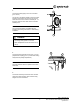


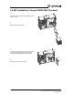

Table Of Contents

Topvex Series
HWC - Hot Water Coil,
ELP - Electric Pre-Heater installation instructions
Systemair Inc.
8
5
Connect the water piping to the coil connections
(pos.1 and 2).
Thearrowsintheguresdisplayhowthehotwater
should be connected to the coil. Connect the hot
water inlet to the tube connection marked pos. 1 in
thegure,andthereturnwatertotheconnection
marked pos. 2.
Note:
The unit in the illustration is installed with the
inspection door facing downward, i.e. false ceiling
installation.
Caution
• Take care not to damage the water coil when
connecting water pipes.
• Water temperature should not exceed 194°F
(90°C).
1 Warnings
The following admonitions will be presented in the different sections of the document.
Danger
• Make sure that the Mains supply to the unit is disconnected before performing any maintenance or
electrical work!
• All electrical connections must be carried out in accordance with local rules and regulations.
Warning
• In order for the unit to be considered safely installed the doors if equipped with handles have to be
locked with a key to prevent unauthorized or accidental opening
• The unit must be duct connected or in some other way provided with protection so that it is not
possible to come in contact with the fans through the duct connections
• The unit is heavy. Be careful during transport and mounting. Risk of injury through pinching. Use
protective clothing.
• Beware of sharp edges during mounting and maintenance. Make sure that a proper lifting device is
used. Use protective clothing.
Caution
• If the unit is installed in a cold place make sure that all joints are covered with insulation, and tape well
• Duct connections/duct ends should be covered during storage and installation
• Do not connect tumble dryers to the ventilation system
• Take care not to damage the water battery when connecting water pipes to connectors. Use a
spanner to tighten the connection.
Topvex FR03, FR06, FR08, and FR11
Installation instructions
206638
1
Systemair AB
6
Connect the frost protection sensor (pos. 1) to the
prepared fast coupling (pos. 2) on the inside casing
wall (wires are polarity independent).
Note:
The frost protection sensor is placed on the return
water tube.
2
1
2 1
7
Connect all necessary accessories such as water
valves and valve actuators. See enclosed wiring
diagram for more information.