
AMCA 250


I=V × A
IF=
I
Q
Legend (SI) [IP]:
IF = Induction Factor
I = Induced Airow at the throw length
(m
3
/s) [cfm]
V = Average air velocity at the throw length
(m/s) [ft/min]
A = Area of the positive velocity clip at the throw length
(m
2
) [ft
2
]
Q = Airow through the fan housing
(m
3
/s) [cfm]
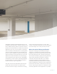
Throw length describes the farthest distance a jet fan
can push air, specied by a terminal velocity of 1 m/s
(196 fpm) at the end of the throw length. The longer
the throw length, the more effective jet fans are in
optimizing garage ventilation systems. Throw length
is dependent on thrust, airow, fan outlet shape, and
airow direction, and is generated from product-
specic CFD analysis using AMCA 250 data. When
comparing throw lengths of jet fans, make sure the
same terminal velocity is used.
Throw
Commonly expressed as feet (ft) or meters (m)
Induction Factor
Calculated through AMCA 250 performance measurements
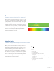
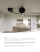
5256 ft/min. 68 214492
Systemair IV50 EC - Contour plot of Velocity magnitude (ft/min) at 1.5 meter Height from Ground of Garage
in Horizontal Plane
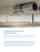
When air is thrusted forward through the outlet of a
jet fan, high volumes of air surrounding the outlet are
pulled with the discharged air. This process is called
induction. Inducing airow reduces ‘dead spots’ in a
large, open space, like a parking garage. To quantify
the induction of a jet fan, an induction factor equation
is used. A higher induction factor means that a fan is
better at entraining the stagnant surrounding air. The
induction factor is generated from product-specic
CFD analysis using AMCA 250 data.
systemair 3