
SAVE VTR 150B INSTALLATIONV01 20210316
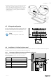
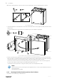
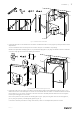

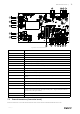
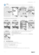

Table Of Contents
- 1 Overview
- 2 Important Safety Information
- 3 Technical Data
- 4 Delivery, Transport, Storage
- 5 Prerequisites for Installation
- 6 Installation
- 7 Electrical connections
- 8 Before Starting the System
- 9 Commissioning
- 10 Concluding Routines
- 11 Disposal and recycling
- 12 EU Declaration of Conformity

Electrical connections |
19
Fig. 25 Main circuit board connections
Position Description
CB
Connection to the external connection box
1
Terminals for a heater
2
Terminals for a TRIAC
3
Terminals for the mains power supply
4
Terminals for power supply of extract air fan
5
Terminals for power supply of supply air fan
6
Terminals for internal relative humidity/temperature sensor
7
Analog input 1 — Outdoor air sensor
8
Analog input 2 — Supply air sensor
9
Analog input 3 — Freely configurable
10
Analog input 4 — Freely configurable / Overheat temperature sensor (units with
heater)
11
Analog input 5 — Freely configurable
12
Digital input 1 — Rotor guard sensor (only for VSR, VTR models)
13
Digital input 2 — Freely configurable / Cooker hood (VTR 150/K unit)
14
Analog output 2 — Freely configurable / Electrical heater controller (VTC 700 unit)
15
Analog output 1 — Rotary heat exchanger control signal (for VSR, VTR type models) /
Damper control signal (for VTC, VSC type models), UI6 — Bypass damper feedback
signal (for VTC, VSC type models)
16
Terminals for speed control of extract air fan
17
Terminals for speed control of supply air fan
7.2 External connections (Connection board)
External connections to the main circuit board are done via connection board situated inside of the unit.
254539 | v2