SAVE VTR 150/B Service & Accessories Installation Manual GB Document in original language | · v1.
© Copyright Systemair UAB All rights reserved E&OE Systemair UAB reserves the rights to change their products without notice. This also applies to products already ordered, as long as it does not affect the previously agreed specifications. Systemair is not liable or bound by the warranty if these instructions are not adhered to during installation or service. | v1.
Contents 1 2 3 4 5 Overview ......................................................1 1.1 Warranty ..............................................1 1.2 Type label.............................................1 1.3 Disposal and recycling .............................1 Important Safety Information .............................1 2.1 Intended Use.........................................2 2.2 Admonitions .........................................2 Configuration .................................................
Overview | 1 Overview The key to proper and safe operating of the unit is to read this manual thoroughly, use the unit according to given guidelines and follow all safety requirements. 1.1 Warranty For the assertion of warranty claims, the products must be correctly connected and operated, and used in accordance with the data sheets. Further prerequisites are a completed maintenance plan with no gaps and a commissioning report. Systemair will require these in the case of a warranty claim. 1.
2 | Configuration • Do not allow children to play with the device. 2.1 Intended Use • Abide by the system-related conditions and requirements of the system manufacturer or plant constructor. • Keep all the warning signs on the device and in a legible condition. • The device is not to be used by persons (including children) with reduced physical, sensory or mental capabilities, or lack of experience and knowledge, unless they have been given supervision or instruction.
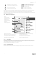
Configuration | On and Off slider to activate or deactivate a function. White bubble — function is inactive, green bubble — function is active. Back button to return to a previous menu, located at the upper left corner Up arrow to increase a value CANCEL Button to cancel changes Down arrow to decrease a value SET/OK Buttons to confirm changes Some menus have more than one page. Touch page indicator in the top right corner to go to the next page.
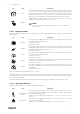
4 | Configuration Icon Text Description AUTO Automatic airflow control. AUTO mode is available for selection when Demand Control, Week Schedule and/or external fan control functions are configured, otherwise AUTO mode icon won’t be visible in active user modes menu. AUTO mode activates Demand Control, Week Schedule and/or external fan control functions. Demand is available to choose as airflow setting in Week Schedule. Manual selection of airflow levels.
Configuration | Icon Text Description Configurable Digital Input 1 Configurable digital input for custom user function. Airflow levels for both fans are freely configurable. High–priority function. Configurable Digital Input 2 Configurable digital input for custom user function. Airflow levels for both fans are freely configurable. Mid–priority function. Configurable Digital Input 3 Configurable digital input for custom user function. Airflow levels for both fans are freely configurable.
6 | Configuration 3.3.2 Temperature settings Temperature can be set at SET TEMPERATURE menu accessible from the home screen by touching TEMPERATURE icon with thermometer. Default temperature value is 18°C (range 12–30°C). Use up and down arrows or a slider to change the value. Then touch the OK button to confirm changes. Temperature set point is for room air temperature, supply air temperature or for extract air temperature depending on which control mode is active.
Configuration | Use up and down arrows or a slider to change the airflow value. The airflow may be adjusted in these steps: Off/Low/Normal/High. These settings control output signals to the supply and extract fans. Important It is not recommended to set fan to Off in standard households. If manual fan stop is activated, the unit should be provided with dampers in exhaust and fresh air ducts to avoid cold draught and risk of condensation when the unit has been stopped.
8 | Configuration Icon 3.5 3.5.1 Text Description Cooling recovery Automatic cooling recovery is active when extract air temperature from apartment is lower than outdoor air temperature and there is a cooling demand (temperature setpoint is lower than outdoor air temperature). No cooling recovery with heating demand. If the outdoor air temperature is higher than then thee indoor air temperature and there is a heating demand, function Free heating is activated instead.
Configuration | 3.5.1.2 Sensors Values from sensors and load of fans (rpm). 3.5.1.3 Input Status Status of configured analog, digital and universal inputs. Connected component type and raw value (volts) is displayed. 3.5.1.4 Output Status Status of configured analog, digital and universal outputs. Connected component type and value (volts) is displayed. 3.5.1.5 Unit Version Unit model name, manufacturer number, serial number and unit software versions for Mainboard, HMI and IAM. 3.5.
10 | Configuration Alarm name Explanation Do the following Defrosting error Indicates failure of pre-heater to preheat the incoming outdoor air (in case Extra controller is configured as Preheater). Check the pre-heater reset button. Check the pre-heater cabling. Contact your installation company or place of purchase. Defrosting error may be caused by extremely low outdoor air temperatures or pre-heater failure. • Alarm stops the unit.
Configuration | Alarm name Explanation Do the following Rotor motor feedback Indicates a rotor malfunction. No feedback signal from the rotor motor for 180 seconds. If the rotating heat exchanger has stopped, check the rotor belt. Replace the belt if it is broken. If the heat exchanger is still not rotating check if the quick connector of the rotary heat exchanger motor is connected. If the alarm persists, the motor may be faulty. Contact your installation company or place of purchase.
12 | Configuration Alarm name Explanation Do the following Built-in extract air temperature sensor Indicates internal extract air temperature sensor malfunction. Active: measured temperature = 0°C Returned: measured temperature > 5°C Check that sensor is connected properly and cable is not damaged. Contact your installation company or place of purchase. Extra controller alarm Error from external device. Check if external device is connected properly and cable is not damaged.
Configuration | 3.5.3 Week Schedule The unit can be configured to operate at set airflow levels up to two time periods (00:00–23:59) on user selected days. Week Schedule is active only during AUTO mode. It is possible to activate or deactivate digital output for schedule and unscheduled periods. 3.5.3.1 Schedule Airflow Settings Touch settings icon to go to SCHEDULE AIRFLOW SETTINGS menu. In this menu set airflow level for scheduled and unscheduled periods.
14 | Configuration Set the time. Touch the START TIME or END TIME values to change time. Use arrow buttons decrease value. Confirm with OK button. and to increase or Note: Scheduled time can start but never end at midnight (00:00). The latest END TIME period is 23:59. Scheduled time cannot go to the next day. 12 or 24 hour time format can be changed in System Preferences menu. If necessary, activate second scheduled period and set up time.
Configuration | 3.5.6.1 Input Configuration of inputs Settings for analog, digital and universal input terminals on the main board and connection board, configuration of functionality. Table 1 Digital universal inputs available for selection User Modes Activation of specific user modes. Central Vacuum Cleaner Function Activation of Central vacuum cleaner function. Cooker Hood Function Activation of Cooker Hood function. External Stop Air handling unit is stopped by an external command.
16 | Configuration Table 3 Digital outputs available for selection Step Controller Y1 Heating Step Controller Y3 Cooling Step Controller Y4 Extra Controller Heater/Cooler/Extra controller control signals. Sum Alarm Fault indicating output. Outdoor-/Exhaust Air Damper Outdoor-/Exhaust air damper control signal. Secondary air Secondary air damper control. Activate Cooling Cooling mode activation signal to an external system.
Configuration | Range: 0–10 V / 2–10 V / 10–0 V / 10–2 V. Heater • Choose heater type. Each selection unlocks additional configuration options. Default setting is based on unit type. Available types: None / Electrical / Water / Change-over. • Set actuator type. Default value is 0–10 V. Range: 0–10 V / 2–10 V / 10–0 V / 10–2 V. • Set circulation pump temperature. Default setting is 10°C. This option is available if Water / Change-over heater type is selected. Range: 0–20°C. • Set circulation pump stop delay.
18 | Configuration 3.5.6.4 Control Regulation Configure how the system is controlled. Temperature Control • Configure temperature controller. Choose control mode: Available modes: Supply air temperature control / Room temperature control / Extract air temperature control Note: Room temperature control mode requires an accessory to measure room temperature. • Choose temperature unit. Default setting is Celsius. Available units: Celsius / Fahrenheit • Set P-band. Default setting is 20°C. Set I-time.
Configuration | Setting Manual RPM Pressure (VAV) Flow (CAV) External Pressure Sensors — configure sensor voltage relation to pressure. Set value at which fan alarm occurs. Default setting is None - - Supply air fan control sensor: Pressure at 0V: 0-500 Pa, default setting 0 Pa Pressure at 10V: 0-2500 Pa, default setting 500 Pa. Extract air fan control sensor: Pressure at 0V: 0-500 Pa, default setting 0 Pa.
20 | Configuration Setpoint, default setting is 45% humidity. Range: 1–100% RH. Set P-band, default setting is 4g/kg. Range: 1–100g/kg. Set I-time, default setting is Off. Range: Off/1–120 sec. Defrosting Control Note: Setting is available if heat exchanger type is set as Plate. The unit is equipped with an automatic defrost function that is activated when there is risk of icing in the area around the heat exchanger. • Select defrosting mode. Default setting is Normal.
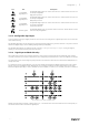
Configuration | Fig. 4 Example speed for supply and extract air 4. Use this procedure to find fan speed for all airflow levels: MINIMUM LEVEL, LOW LEVEL, NORMAL LEVEL, HIGH LEVEL, MAXIMUM LEVEL. 5. Finally in the control panel go to Service menu, enter the password, then go to Control Regulation → Fan Control. Choose RPM as airflow type and in sub-menu Airflow Level Settings enter calculated fan speed values for each level. 3.5.6.5 User Modes Set airflow level, duration and offset for each user mode.
22 | Configuration Connecting the IAM to wireless network 1. If your wireless router does not support WPS, Wi-Fi connection should be set up manually. Therefore you need to find Wi-Fi name and add password using control panel. 2. In control panel go to Service -> Communication -> WLAN settings menu. 3. Press Scan for networks button. IAM will search for available Wi-Fi networks (should not take longer than one minute). 4.
Service | 3.5.7 Help FAQ, troubleshooting of alarms, contact information for support is provided in this menu. • Service partner — information about service partner. • Company • Telephone • Homepage • Email • User modes— detailed description of all user modes. • Functions— detailed description of different user functions. • Alarms— detailed description of all alarms. • Troubleshooting— information about all different possible malfunctions. 4 Service 4.
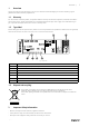
24 | Service 4.3 Internal components Fig. 5 Internal components Position Description 1 Mounting bracket 2 External connections 3 Main print card 4 Supply air fan 5 Internal electrical heater (500/1000 W) 6 Extract air filter 7 Supply air filter 8 Extract air fan 9 Rotating heat exchanger 10 Supply air sensor 11 Outdoor air sensor 12 Relative humidity/Extract air temperature sensor 13 Overheat protection sensor 4.3.1 Component description 4.3.1.
Service | 4.3.1.3 Heat exchanger SAVE VTR 150/B is equipped with a rotating heat exchanger. Required supply air temperature is therefore normally maintained without adding additional heat. The heat exchanger is removable for cleaning and maintenance, see “User Manual” for more information. 4.3.1.4 Main circuit board The main circuit board controls all functions and the unit. It is possible to connect external accessories to a free terminals on the main circuit board. 4.3.1.
26 | Service Fig. 6 Main circuit board position 4.4.1 Main circuit board layout The SAVE VTR 150/B is equipped with built-in regulation and internal wiring. Fig.
Service | Position Description 8 Analog input 2 — Supply air sensor 9 Analog input 3 — Freely configurable 10 Analog input 4 — Freely configurable / Overheat temperature sensor (units with heater) 11 Analog input 5 — Freely configurable 12 Digital input 1 — Rotor guard sensor (only for VSR, VTR models) 13 Digital input 2 — Freely configurable / Cooker hood (VTR 150/K unit) 14 Analog output 2 — Freely configurable / Electrical heater controller (VTC 700 unit) 15 Analog output 1 — Rotary heat
28 | Service Position Description UI1–5 Freely configurable universal input. Can be set as analog input (0–10 V) or a digital input (24 V). UI1 default configuration: Pressure guard UI2 default configuration: Cooker hood UI3 default configuration: Fire alarm UI4 default configuration: Refresh 24V Maximum current 200mA at 24VDC +-10%. 4.5 Troubleshooting If problems should occur, please check the items below before calling your service representative. Fans do not start 1.
Accessories | Noise/vibrations 1. Clean fan impellers. 2. Check that the screws holding the fans are tightened. 3. Check that the anti vibration lists are fitted to the mounting bracket and to the back of the unit. 4. Check that the rotor belt is not slipping if the unit has rotating heat exchanger. 5 Accessories SAVE VTR 150/B have many available accessories that can be used to expand functionality of the unit and increase comfort level.
30 | Accessories Note: The internet access module uses TCP port 8989. Make sure it is not blocked. Description A. Connect the Internet Access Module (IAM) to the Connection Board (CB) with included RJ10 cable. B. Power up the IAM with included power supply cable and adapter (230 V~). C. Enable access to the internet. Three options are available: • C1 — Activate WPS function on your router (if available) and press the button on the Internet Access Module for 5 seconds.
Accessories | Press LOG IN button. It is required to create a unique password when connecting to IAM for the first time. Touch Change password button. In the next menu screen enter your new password, confirm it and touch SET PASSWORD button. To finalize password creation, click the button on the IAM. Wait for a message to pop up in your app telling that password was changed. Touch BACK button to return to the previous login screen. Enter the newly created password and touch LOG IN button.
32 | Accessories Configuration 1. Go to Service menu. 2. Enter password (default 1111). 3. Configure of CO2 and/or relative humidity sensor: Go to Input menu. Select UNIVERSAL tab. Select the universal input to which the sensor is connected. Example if it is connected to UI4 on the connection board, then select UNIVERSAL INPUT 4. Select signal type as Analog input and select sensor type from the input type list: RH sensor (RH) and/or CO₂ Sensor (CO₂). 4. Configure room temperature sensor: Go to Input menu.
Accessories | Outdoor air heater configuration 1. Go to Service menu 2. Enter password (default 1111) 3. Set the heater type: Components —> Extra Controller —>Extra Controller Mode —> Preheater. 4. Configure connection of the pre-heater. Go to Service menu. Select Output menu. In next menu select DIGITAL tab. Select the digital output to which the pre-heater is connected.
34 | Accessories Supply air heater configuration 1. Go to Service menu 2. Enter password (default 1111) 3. Set the heater type: Components > Extra Controller > Extra Controller Mode > Heating. 4. Configure connection of the heater. Go to Service menu. Select Output menu. In next menu select DIGITAL tab. Select the digital output to which the heater is connected.
Accessories | Note: A duct temperature sensor can be connected to analog inputs 6–7 on the connection board for better access and then configured as a supply air temperature sensor. However the internal supply air temperature sensor must be disabled in the control panel first. Configuration 1. Go to Service menu 2. Enter password (default 1111) 3. Activate the actuator. Go to Components menu, select Heater menu and select type as Water. Choose actuator voltage type. Do advanced settings if necessary. 4.
36 | Accessories Installation and connection 1. Install a duct water cooler in the duct. Connect pipes, 2/ 3–way valve and actuator. Important Do NOT use 24V DC power output from the connection board for valve actuator. Fig. 11 Duct cooler connections 2. Connect actuator (S) to any free analog output. 3. An internal supply air temperature sensor (SAT, default connection AI2 on the main circuit board) must be replaced by a duct temperature sensor which can be acquired as an accessory.
Accessories | • GHT — Ground heat exchanger • ECT — extra controller temperature sensor • OAT — outdoor air duct temperature sensor • RL — relay • 1 — Outdoor air • 2 — Supply air • 3 — Extract air • 4 — Exhaust air Installation and connection 1. Install the ground heat exchanger (GE) at least 100 mm distance from the unit in the outdoor air duct. Relay (RL) is used to control the ground heat exchanger. Connect the relay to any free digital output on the connection board (CB). 2.
38 | Accessories Important The change-over (heating/cooling) system can be implemented in many different ways and may vary in each household. This description explains the most common solution for connecting and controlling heating and cooling with a water coil and a heat pump.
Accessories | Fig. 12 Change-over heating/cooling connections Configuration Before change-over heating/cooling can be activated, all components must be configured in the control panel. 1. Go to Service menu 2. Enter password (default 1111) 3. Go to Components menu, select Heater menu and select type as Change-over. Do advanced settings if necessary. Go to Components menu, select Cooler menu and select type as Change-over. Do advanced settings if necessary. 4.
40 | Accessories • SPI-125 C Iris damper — 6751 Installation and connection • Follow instructions in the manual which is delivered with the accessory. 5.5 5.5.1 Installation/Maintenance Outdoor/Exhaust air dampers If manual fan stop is activated, the unit should be provided with dampers in exhaust and outdoor ducts to avoid cold draught and risk of condensation when the unit has been stopped.
Accessories | Note: 24 VAC dampers can be powered and controlled only by using a relay mounting kit with a transformer (article number: 153548). This installation procedure describes how to connect dampers powered by 230 V~ with a relay mounting kit without transformer (article number: 153549). Installation and connection 1. Install dampers (U/V). 2. Connect control signal wires (24V, DO) coming out from the relay box (RL) to any free digital output on the connection board (CB). 3.
42 | Accessories 1. A differential pressure switch 2. Metal tube 3. Exhaust air direction 4. Exhaust air duct 1. Mount a differential pressure switch in a suitable place, for example on or near the outlet duct from the kitchen fan. Set the pressure switch to the lowest possible pressure, for example 20 Pa. 2. There are two possible installation cases. A pressure switch tube is installed in the duct: a.
Accessories | Note: • If the 24 V power supply on the connection board (CB) is used for other equipment, the number of control panels that can be powered from the unit will decrease. • A single active control panel draws 50 mA. The connection board supplies up to 250 mA. If no other accessories use 24 V power supply from the unit, up to 5 control panels can be connected without a need of external power supply. In order to connect more than 5 control panels, an external power supply is required.
44 | Accessories Universal input can be easily re-configured to activate a different function. Component/product — Article number: • Presence detector/IR24 — 6995 Configuration 1. Go to Service menu 2. Enter password (default 1111) 3. Go to Input menu. Select UNIVERSAL tab. 4. Select the universal input to which wire from the presence detector is connected. If, for example, it is connected to UI3 on the connection board, then select UNIVERSAL INPUT 3.
| v1.
Phone +370 340 60165 Fax +370 340 60166 www.systemair.com SAVE VTR 150/B · · · en_GB · 2021-04-21 · v1.1 Systemair UAB Linų st.