SAVE VTR 300/B Installation instructions Document in original language | 333561 · v1.
© Copyright Systemair UAB All rights reserved E&OE Systemair UAB reserves the rights to alter their products without notice. This also applies to products already ordered, as long as it does not affect the previously agreed specifications. Systemair is not liable or bound by warranty if these instructions are not adhered to during installation or service. 333561 | v1.
Contents 1 Overview ......................................................1 1.1 General Description ................................1 1.2 Warranty ..............................................1 1.3 Type label.............................................1 2 Important Safety Information .............................1 2.1 Intended Use.........................................1 2.2 Admonitions .........................................2 3 Technical Data ................................................2 3.
Overview | 1 Overview 1.1 General Description Read the instructions carefully and in its entirety. For description of advanced settings and installation of accessories see Service and Accessories Installation manual. All documents can be found in our online catalogue at www.systemair.com. 1.2 Warranty For the assertion of warranty claims, the products must be correctly connected and operated, and used in accordance with the data sheets.
2 | Technical Data • The system should operate continuously, and only be stopped for maintenance/service. • Do not connect tumble dryers to the ventilation system. • Make sure that filters are mounted before starting the unit. 2.
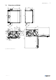
Technical Data | 3.1 Dimensions and Weight 491 234** 879 842 823 800 762 210** 1504 353 258 ø125 298 131 116 211 104 97 201 255 108* 746 50* 779 78* 1207 ø160x4 Fig. 2 Dimensions of left hand unit 333561 | v1.
4 | Technical Data 762 879 842 800 823 491 210** 234** 354 1504 255 258 201 306 97 136 211 291 104 746 107* ø160x4 1207 ø125 50* 779 78* Fig. 3 Dimensions of right hand unit * Water coil connections. ** Drainage. The unit weight is 56 kg. 3.2 Connections Left and Right models 333561 | v1.
Delivery, Transport, Storage | Position Description R Right hand model (Supply air connection is situated on the right hand side of the unit viewed from the front) L Left hand model (Supply air connection panel is situated on the left hand side of the unit viewed from the front) Symbol 3.3 Description Symbol Description Supply air Outdoor air Exhaust air Extract air Symbol Description Cooker hood air Installation recommendation regarding condensation 3.3.
6 | Prerequisites for Installation Important • Use the packaging exclusively as transport protection and not as a lifting aid. • Load and unload the air handling unit carefully. 4.2 Delivery/Unloading The appliance is delivered in one piece containing all necessary components, wrapped in plastic on a pallet for easy transportation. Checking delivery • Check the packaging and the air handling unit for transport damage. Any findings should be noted on the cargo manifest.
Installation | Note: The drainage connection is plugged in the bottom of the unit at delivery. To use the drainage: remove the rubber seal and connect the drainage pipe. Connect the drainage pipe to the sewer. The water can not be led straight to the sewer without a water trap. 5.
8 | Installation X* — adaptable height according to needs. Make sure the mounting bracket is completely level. Follow the ventilation drawing when connecting the unit to the duct system. 6.1 Ventilation Duct Connection and Insulation Important • Always cover the ventilation ducts during construction period. • Make sure there are no loose objects or impurities inside the ducts. Install the ducts, supply air diffusers and air intake grilles as shown in the ventilation drawing.
Electrical connections | It is very important to insulate cold ducts and joints tightly without any gaps, otherwise there is a risk of condensation which may result in moisture damage. Do not install the ducts directly against structural building elements to avoid sound propagation. Use acoustic insulation and sound attenuators. Note: The type of ventilation ducts and insulation differ for each building and climate zone.
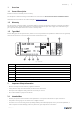
10 | Electrical connections Position Description CB Connection to the external connection box 1 Terminals for a heater 2 Terminals for a TRIAC 3 Terminals for the mains power supply 4 Terminals for power supply of extract air fan 5 Terminals for power supply of supply air fan 6 Terminals for internal relative humidity/temperature sensor 7 Analog input 1 — Outdoor air sensor 8 Analog input 2 — Supply air sensor 9 Analog input 3 — Freely configurable 10 Analog input 4 — Freely configur
Before Starting the System | Position Description DO1–4 Freely configurable digital output. DO2 default configuration: Outdoor-/Exhaust Air Damper DO3 default configuration: Activate Cooling DO4 default configuration: Sum Alarm AO3–5 Freely configurable analog output. Actuator type 0–10V, 10–0V, 2–10V, 10–2V. AO3 default configuration: Heating (only for VTC 200/300/500/700, VTR 100/700 type models). AO4 default configuration: Cooling UI1–5 Freely configurable universal input.
12 | Concluding Routines Set speed of supply and extract air fans for each level. When finished, review your settings. It is possible to go back to previous menus and make modifications. Choose heating type or none. Reset filter changer timer if necessary. Finish startup wizard with OK button. All additional changes post-startup wizard must be recorded in the Commissioning record. 10 Concluding Routines Perform the following procedures before leaving the site: 1.
EU Declaration of Conformity | 12 EU Declaration of Conformity Manufacturer EN 50106 Systemair UAB Linų st. 101 LT–20174 Ukmergė, LITHUANIA Office: +370 340 60165 Fax: +370 340 60166 www.systemair.com Safety of household and similar appliances – Particular rules for routine tests referring to appliances under the scope of EN 60 335-1. EN 60529 Degrees of protection provided by enclosures (IP Code).
Phone +370 340 60165 Fax +370 340 60166 www.systemair.com SAVE VTR 300/B · Installation instructions · 333561 · en_GB · 2022-05-27 · v1.1 Systemair UAB Linų st.