SAVE VTC 700 Installation instructions Document in original language | 254492 · v01 GB
© Copyright Systemair UAB All rights reserved E&OE Systemair UAB reserves the rights to alter their products without notice. This also applies to products already ordered, as long as it does not affect the previously agreed specifications. Systemair is not liable or bound by warranty if these instructions are not adhered to during installation or service.
Contents 1 Overview ......................................................1 1.1 General Description ................................1 1.2 Warranty ..............................................1 1.3 Type label.............................................1 2 Important Safety Information .............................1 2.1 Intended Use.........................................1 2.2 Admonitions .........................................2 3 Technical data ................................................2 3.
Overview | 1 Overview 1.1 General Description Read the instructions carefully and in its entirety. For description of advanced settings and installation of accessories see Service and Accessories Installation manual. All documents can be found in our online catalogue at www.systemair.com. 1.2 Warranty For the assertion of warranty claims, the products must be correctly connected and operated, and used in accordance with the data sheets.
2 | Technical data • The system should operate continuously, and only be stopped for maintenance/service. • Do not connect tumble dryers to the ventilation system. • Make sure that filters are mounted before starting the unit. 2.
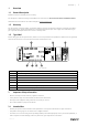
Technical data | 3.1 Dimensions and weight Fig. 2 Dimensions of right hand unit * Drainage. ** Height with mounting bracket. The unit weight is 160 kg. 3.2 Duct connections Table 2 Symbol description Symbol Description A Supply air B Exhaust air C Outdoor air C D B A R D 254492 | v01 Extract air Fig.
4 | Delivery, Transport, Storage Position 3.3 3.3.1 Description R Right hand model (Supply air connection is situated on the right hand side of the unit viewed from the front) L Left hand model (Supply air connection is situated on the left hand side of the unit viewed from the front) Installation recommendation regarding condensation Condensation inside of the unit When the unit is installed in a cold attic (close to outdoor temperature) the unit should run continuously.
Prerequisites for Installation | Checking delivery • Check the packaging and the air handling unit for transport damage. Any findings should be noted on the cargo manifest. • Check completeness of the delivery. Verify that all ordered equipment is delivered before starting the installation. Any discrepancies from the ordered equipment must be reported to the supplier of Systemair products.
6 | Installation 5.2 Outdoor Air Intake Location Recommendation Recommended installation location for the outdoor air intake is the northern or eastern side of the building and with a distance to openings for discharge of stale ventilation air, kitchen ventilator, central vacuum system, waste water drainage and other pollution sources like exhaust from traffic, etc. Exhaust air should ideally be led via a roof cowl to the outside and with a good distance from the outdoor air intake, windows, etc. 5.
Electrical Connections | 3 Connect the condensate drainage to the 2 drain plugs in the bottom of the unit. Make sure to use correct drain traps on both connections. The height (H) must be at least 60 mm. Drain traps are not included on delivery and can not be obtained from Systemair. Note: Remove caps from the drainage holes inside the unit. 4 Connect the unit to the duct system. Make sure that all necessary accessories are used to create a functional ventilation solution.
8 | Electrical Connections 1 Remove the front hatch by the use of an 8 mm Allen key, after which the hatch is tilted back and lifted off completely. 2 Open the side panel by removing 4 screws. 3 Remove the top cover plate (pos. 1) by removing 2 screws (pos. 2) in the lower front edge of the plate. All external connections to possible accessories are made to terminals on the connection box (chapter 7.2). 7.
Electrical Connections | Position Description CB Connection to the external connection box 1 Terminals for a heater 2 Terminals for a TRIAC 3 Terminals for the mains power supply 4 Terminals for power supply of extract air fan 5 Terminals for power supply of supply air fan 6 Terminals for internal relative humidity/temperature sensor 7 Analog input 1 — Outdoor air sensor 8 Analog input 2 — Supply air sensor 9 Analog input 3 — Freely configurable 10 Analog input 4 — Freely configurable
10 | Before Starting the System Position Description DO1–4 Freely configurable digital output. DO2 default configuration: Outdoor-/Exhaust Air Damper DO3 default configuration: Activate Cooling DO4 default configuration: Sum Alarm AO3–5 Freely configurable analog output. Actuator type 0–10V, 10–0V, 2–10V, 10–2V. AO3 default configuration: Heating (only for VTC 200/300/500/700, VTR 100/700 type models). AO4 default configuration: Cooling UI1–5 Freely configurable universal input.
Concluding Routines | Set speed of supply and extract air fans for each level. When finished, review your settings. It is possible to go back to previous menus and make modifications. Choose heating type or none. Reset filter changer timer if necessary. Finish startup wizard with OK button. All additional changes post-startup wizard must be recorded in the Commissioning record. 10 Concluding Routines Perform the following procedures before leaving the site: 1.
12 | EU Declaration of Conformity 12 EU Declaration of Conformity Manufacturer EN 60529 Systemair UAB Linų st. 101 LT–20174 Ukmergė, LITHUANIA Office: +370 340 60165 Fax: +370 340 60166 www.systemair.com The manufacturer hereby confirms that SAVE VTC 700 comply with all applicable requirements in the following directives and regulations.
254492 | v01
Phone +370 340 60165 Fax +370 340 60166 www.systemair.com SAVE VTC 700 · Installation instructions · 254492 · en_GB · 2021-03-15 · v01 Systemair UAB Linų st.