SWS SE ...15 FR ... 30 EN ... 18 NO ... 21 DE ... 24 ES ... 27 IT NL ... 36 PL ... 39 RU ... 42 ....
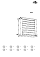
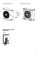
SWS Fan heater SWS 3 1. 2. 3. 4. Fan heater SWS Mounting brackets SWB Basic filter SWSFT Filter section, deep-pleated bagfilter EU3 SWF 5. Return air intake SWD 6. Extra air director SWLR 7.
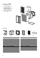
SWS Dimensions G J Inlet H A I Outlet F ø B D K E C Type A [mm] B [mm] C [mm] D [mm] E [mm] F [mm] G [mm] H [mm] I [mm] J [mm] K [mm] Ø [mm] SWS02 SWS12 SWS22 SWS32(3) SWS33(3) 470 545 675 800 520 540 690 830 210 215 215 315 50 60 60 35 95 95 100 100 40 40 45 45 70 70 70 70 40 40 45 45 390 465 585 710 65 65 70 70 260 260 400 530 22 22 28 28 Mounting brackets SWB Filter section, SWF E D I D G ø20 C F B A 50 288 H Type A [mm] B [mm] C [mm] D [mm] SWB0
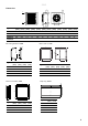
SWS Minimum distance min 850 mm Controls 15 10 20 5 30 25 TKS16 KRT1900 Type Description TKS16 Electronic thermostat with knob and 1-pole main switch HxWxD [mm] 80x80x31 KRT1900 Capillary tube thermostat 165x57x60 S-DT16 Thermal contact motor protection (400V3~) 135x80x97 SWYD1 2-step change-over switch for air flow (Y/D) 120x85x135 Water regulation SD20 Type RSK SD20 672 70 37 TVVS20 673 92 96 TVVS25 673 92 97 TVVS20/25 + TVVS20/25 4 SD20
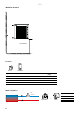
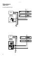
SWS Electrical installation 230V~ Electrical installation 400V3~ Terminal box 1 m cable Wiring diagrams SWS SWS 230V~ Internal Yellow-Green Brown Black Blue M ~ L N 1 2 L N 230 V~ 5
SWS Wiring diagram SWS 230V~ Control by thermostat only SD20 TVVS20/25 SWS L N 1 2 SWS L N 1 2 3 2 1 KRT L N 230 V~ SD20 TVVS20/25 A/B TKS16 >t°C 5 6 7 2 2o 4 L N 230 V~ 6 SWS L N 1 2 SWS L N 1 2
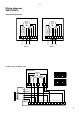
SWS Wiring diagrams SWS 400V3~ Internal wiring diagram SWS323/333 SWS323/333 ∆ 400V3~ Black Orange Brown Red Blue Grey M ~ Black Orange Brown Red Blue Grey M ~ U1 V2 V1 W2 W1 U2 TK TK L1 L2 Y 400V3~ U1 V2 V1 W2 W1 U2 TK TK L1 L3 L2 L3 400 V3~ 400 V3~ 2-step control of airflow only SWS323/333 M ~ V2 TK TK U1 Red Blue Brown Grey Black Orange Full speed V1 U2 W2 W1 Half speed S-DT16 TK TK L3 5 6 L2 3 4 L1 1 2 SWYD1 1 2 3 4 5 6 7 8 9 10 11 12 13 14 15 16 17 18
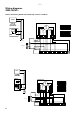
SWS Wiring diagrams SWS 400V3~ Heat controlled by thermostat and 2-step control of air flow SD20 SWS323/333 TVVS20/25 M ~ 3 2 1 KRT V2 TK TK U1 Red Blue Brown Grey Black Orange Full speed V1 U2 W2 W1 Half speed S-DT16 L N 230 V~ 400 3V~ TK TK L3 5 6 L2 3 4 L1 1 2 SWYD1 1 2 4 3 5 6 7 8 9 10 11 12 13 14 15 16 17 18 19 20 SD20 TVVS20/25 TKS16 A/B SWS323/333 V2 TK TK U1 Red Blue Brown Grey Orange Full speed Black >t°C M ~ 5 6 7 2 2o 4 V1 U2 W2 W1 Half speed L
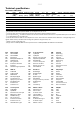
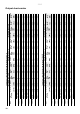
SWS Technical specifications Fan heater SWS (IP44) Type SWS02*7 Heat Airflow Air flow output*1 [kW] [m3/h] [m3/s] 12 1260 0,35 Sound power*2 [dB(A)] 65 Sound ∆t*1,4 pressure*3 [dB(A)] [°C] 50 16 Air throw*5 [m] 7 Water Voltage volume*6 [l] [V] 1,3 230V~ Amperage Weight [A] 0,36 [kg] 14 SWS12*7 19 2340 0,65 73 57 13 10 1,5 230V~ 0,63 18 SWS22 30 3560 0,99 74 58 14 14 2,7 230V~ 0,94 26 SWS32 50 6300 1,75 80 64 13 19 3,8 230V~ 2,16 45 SWS33 65 6090 1,69 80 64
1260 520 2340 620 3560 860 6300 1540 6090 1550 5890 4400 5660 4300 [m³/h] Fan Airflow position max min (80V) SWS12 max min (80V) SWS22 max min (80V) SWS32 max min (80V) SWS33 max min (80V) SWS323 max D min Y SWS333 max D min Y SWS02 Type 1260 520 2340 620 3560 860 6300 1540 6090 1550 5890 4400 5660 4300 [m³/h] Fan Airflow position max min (80V) SWS12 max min (80V) SWS22 max min (80V) SWS32 max min (80V) SWS33 max min (80V) SWS323 max∆ min Y SWS333 max∆ min Y SWS02 Type 40 58 29 55 32 61 29 5
1260 520 2340 620 3560 860 6300 1540 6090 1550 5890 4400 5660 4300 1260 520 2340 620 3560 860 6300 1540 6090 1550 5890 4400 5660 4300 [m³/h] Fan Airflow position max min (80V) SWS12 max min (80V) SWS22 max min (80V) SWS32 max min (80V) SWS33 max min (80V) SWS323 maxD minY SWS333 maxD minY SWS02 Type max min (80V) SWS12 max min (80V) SWS22 max min (80V) SWS32 max min (80V) SWS33 max min SWS323 max∆ minY SWS333 max∆ minY SWS02 Type 34 49 25 48 27 52 25 49 39 63 26 31 40 45 0,29 0,05 0,44 0,18 0,7 0
1260 520 2340 620 3560 860 6300 1540 6090 1550 5890 4400 5660 4300 [m³/h] Fan Airflow position SWS02 max min (80V) SWS12 max min (80V) SWS22 max min (80V) SWS32 max min (80V) SWS33 max min SWS323 max∆ minY SWS333 max∆ minY Type 1260 520 2340 620 3560 860 6300 1540 6090 1550 5890 4400 5660 4300 [m³/h] Fan Airflow position max min (80V) SWS12 max min (80V) SWS22 max min (80V) SWS32 max min (80V) SWS33 max min SWS323 max∆ minY SWS333 max∆ minY SWS02 Type 28 42 20 41 22 44 20 42 32 54 21 25 34 38
1260 520 2340 620 3560 860 6300 1540 6090 1550 5890 4400 5660 4300 [m³/h] Fan Airflow position SWS02 max min (80V) SWS12 max min (80V) SWS22 max min (80V) SWS32 max min (80V) SWS33 max min SWS323 max∆ minY SWS333 max∆ minY Type 1260 520 2340 620 3560 860 6300 1540 6090 1550 5890 4400 5660 4300 [m³/h] Fan Airflow position max min (80V) SWS12 max min (80V) SWS22 max min (80V) SWS32 max min (80V) SWS33 max min SWS323 max∆ minY SWS333 max∆ minY SWS02 Type 17 27 10 26 12 29 10 27 20 36 11 14 21 24 0,
1260 520 2340 620 3560 860 6300 1540 6090 1550 5890 4400 5660 4300 [m³/h] Fan Airflow position max min (80V) SWS12 max min (80V) SWS22 max min (80V) SWS32 max min (80V) SWS33 max min SWS323 max∆ minY SWS333 max∆ minY SWS02 Type 13,8 7,6 20,6 8,8 33,5 13 55,7 22,4 74,1 27,7 53,6 45,1 70,8 59,1 14 23 8 22 10 25 8 23 17 32 9 12 18 21 0,17 0,09 0,25 0,11 0,4 0,16 0,67 0,27 0,89 0,33 0,64 0,54 0,85 0,71 9,5 3,2 6,3 1,3 8,4 1,5 13,2 2,5 24,4 4 12,3 9 22,4 16,1 9,7 5,3 14,3 6,1 23,4 9,1 39 15,6 52,2
SWS EN Installation and operating instructions General Instructions Read these instructions carefully before installation and use. Keep this manual for future reference. The product may only be used as set out in the assembly and operating instructions. The guarantee is only valid if the product is used in the manner intended and in accordance with the instructions.
SWS fittings. For correct inlet and outlet connection of the heating coil, see dimension sketch. Note! Be careful while connecting the pipes to prevent pipe damage and water leakage. The heating coil must not be connected to a mains pressure water system or an open water system. Prior to use, the pipe system should be ventilated. The air valve should be connected on a high point in the pipe system. Air and draining valves are not included in the heating coil.
EN SWS Packaging Packaging materials are chosen with consideration to environment and are therefore recyclable. Handling of product at end of working life This product may contain substances necessary for functionality of product but potentially dangerous for the environment. The product should not be disposed mixed with general household waste but delivered to a designated collection point for environmental recycling.
Tel: +46 31 336 86 00 mailbox@frico.se www.frico.net For latest updated information and information about your local contact: www.frico.net.