Spiskåpa 392–10/B Emhætte 392–10/B Cooker hood 392–10/B Kjøkkenhette 392–10/B SV Bruksanvisning Säkerhetsföreskrifter ..................... 3 Installation ...................................... 4 Injustering av luftflöden .................. 7 Användning ..................................... 8 Service och garanti ......................... 9 DA Betjeningsvejledning Sikkerhedsforskrifter .................... 10 Installation .................................... 11 Justering af luftflow ......................
991.0434.
SÄKERHETSFÖRESKRIFTER Läs noga igenom denna bruksoch monteringsanvisning, i synnerhet säkerhetsföreskrifterna, innan du installerar och börjar använda produkten. Spara bruksanvisningen för senare användning eller till den som eventuellt övertar produkten efter dig. Gör produkten strömlös innan all form av rengöring och skötsel. § Avledning av utblåsningsluften skall utföras i enlighet med föreskrifter utfärdade av berörd myndighet.
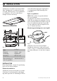
INSTALLATION Spiskåpan är avsedd för montering infälld i skåp. Spiskåpan är försedd med motordrivet spjäll, LED-belysning och metalltrådsfilter. Installation, skötsel, underhåll mm framgår av denna anvisning. TEKNISKA UPPGIFTER enhet alternativt aggregat. Kopplingsbox och vägguttag ska vara åtkomligt efter installation. Byte av spjällucka OBS! Gäller endast när grundventilation sker via spiskåpan. Spiskåpan är försedd med ett tätslutande spjäll.
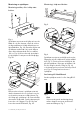
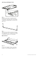
Montering av spiskåpan Montering i skåp med botten Montering mellan, eller i skåp utan botten. Fig. 5 Fig. 3 Spiskåpan monteras med hjälp av konsoler. Märk ut och fäst skruvar, så att de sticker ut några millimeter i båda skåpsidorna enligt måttbilden, Fig. 3A. Om man vill placera spiskåpans undersida i linje med skåpradens undersida används det övre måttet, 102, se Fig. 3A. Konsolerna är justerbara på spiskåpan för att passa olika skåpdjup, Fig. 3B. Fig. 6 Spiskåpan monteras med hjälp av konsoler.
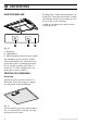
Justering av utdragbar front. Fig. 8 Drag ut fronten helt. Lossa skruven för frontstoppen, på undersidan av spiskåpan och dra den så långt fram mot fronten det går, Fig. 8. Fig. 9 Skjut in fronten tills den hamnar i rätt läge mot skåpraden, Fig. 9. Drag ut fronten igen och dra fast skruven för frontstoppen. Byte av front. Fig. 10 Fronten är löstagbar för byte mot annan frontlist. Lossa skruvarna enligt Fig. 10. 6 991.0434.
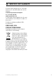
INJUSTERING AV LUFTFLÖDEN SPJÄLLINSTÄLLNING Grundflöde Fig. 13 Forceringsventilationen ställs in genom att skära ut lämpligt antal ringar i strypbrickan, Fig. 13. (Se diagram, sidan 31.) Se till att styrspåret D ligger i läge när brickan åter sitter på plats. Tryckfallsmätning Fig. 11 Grundventilationen ställs in genom att skjutspjället A placeras i önskat läge enligt markering B, Fig. 11. (Se diagram, sidan 32.) Forceringsflöde Fig.
ANVÄNDNING FUNKTION REGLAGE Blötlägg filtret i varmt vatten blandat med diskmedel. Filtret kan även diskas i maskin. Sätt tillbaka fettfilter efter rengöring, se till att de snäpper fast ordentligt. Insidan av spiskåpan ska rengöras minst två gånger per år. Fig. 15 A. Belysning B. Spjällfunktion C. Indikeringslampa (tänd vid öppet spjäll). Vid matlagning öppnas spjället. Spjället stängs automatiskt efter 60 minuter eller genom att trycka en andra gång på knappen B.
SERVICE OCH GARANTI Kontrollera att säkringen är hel. Prova alla funktioner för att säkerställa vad som inte fungerar. Kontakta Systemair kundtjänst tel. +46 222 440 00 www.systemair.com De kan hjälpa till att åtgärda felet eller anvisa till närmaste servicefirma för snabb och bra service. Produkten omfattas av gällande EHLbestämmelser. EMBALLAGE- OCH PRODUKTÅTERVINNING Emballaget ska lämnas in på närmaste miljöstation för återvinning. Symbolen anger att produkten inte får hanteras som hushållsavfall.
SIKKERHEDSFORSKRIFTER Gennemlæs denne betjenings- og monteringsvejledning grundigt, især sikkerhedsforskrifterne, før du installerer og bruger produktet. Gem betjeningsvejledningen til senere brug, eller giv den videre, hvis en anden overtager produktet fra dig. Afbryd altid strømmen til produktet før rengøring og pleje. § Udledning af udgangsluft skal ske i henhold til forskrifter fra respektive myndigheder. § Udgangsluften må ikke ledes ind i røgkanaler, som anvendes til udledning af røggas fra f. eks.
INSTALLATION Emhætten er beregnet til montering indbygget i skab. Emhætten er forsynet med motordrevet spjæld, LED-belysning og metaltrådsfilter. Installation, vedligeholdelse m.m. fremgår af denne vejledning. Elektrisk installation Emhætten leveres med kabel og jordforbundet stik for tilslutning til jordforbundet stikkontakt samt styrekabel for tilslutning til ekstern enhed. Koblingsdåse og stikkontakt skal være tilgængelige efter installationen.
Montering af emhætten Montering i skab med bund Montering mellem skabe eller i et skab uden bund. Fig. 5 Fig. 3 Emhætten monteres ved hjælp af beslag. Afmærk og fastgør skruerne, så de stikker nogle millimeter ud fra begge skabssider som i målskitsen, Fig. 3A. Hvis man vil placere emhættens underside, så den flugter med skabsrækkens underside, anvendes det øverste mål, 102, se Fig. 3A. beslagene kan justeres på emhætten, så de passer til forskellige skabsdybder, Fig. 3B. Fig.
Justering af udtrækkelig front. Fig. 8 Træk fronten helt ud. Løsn skruen til frontstoppet på undersiden af emhætten, og træk den så langt frem mod fronten som muligt, Fig. 8. Fig. 9 Skub fronten ind, til den flugter med skabsrækken, Fig. 9. Træk fronten ud igen, og spænd skruen til frontstoppet fast. Udskiftning af front. Fig. 10 Fronten er aftagelig ved udskiftning med en anden frontliste. Løsn de tre skruer, se Fig. 10. 991.0434.
JUSTERING AF LUFTFLOW SPJÆLDINDSTILLING Grundflow Fig. 13 Den tvungne ventilation indstilles ved at udskære et passende antal ringe i pladen, Fig. 13. (Se diagram, side 31.) Sørg for, at styresporet D er i position, når pladen igen sidder på sin plads. Trykfaldsmåling Fig. 11 Grundventilationen indstilles ved at placere skydespjældet A i ønsket position som angivet ved markering B, Fig. 11. (Se diagram, side 32.) Forceret flow Fig.
BETJENING FUNKTION STYRINGER Læg filteret frit i varmt vand med opvaskemiddel. Filteret kan også vaskes i opvaskemaskine. Monter fedtfilteret igen efter rengøring, sørg for, at det låser korrekt. Emhætten skal rengøres indvendigt mindst to gange årligt. Fig. 15 A. Belysning B. Spjældfunktion C. Indikatorlampe (tændt ved åbent spjæld). Ved madlavning åbnes spjældet. Spjældet lukkes automatisk efter 60 minutter eller ved tryk igen på knappen B.
SERVICE OG GARANTI Kontroller sikringen. Afprøv alle funktionerne for at se, hvad der ikke fungerer. Kontakt Systemair kundeservice tlf. + 45 87387500 www.systemair.dk De kan hjælpe med fejlfinding eller henvise til nærmeste servicefirma for hurtig og god service. Produktet er omfattet af gældende elektriske direktiver. EMBALLAGE- OG PRODUKTGENBRUG Emballagen skal afleveres på nærmeste genbrugsstation til genanvendelse. Symbolet angiver, at produktet ikke må håndteres som husholdningsaffald.
SAFETY INSTRUCTIONS Carefully read these instructions of use and the installation guide, in particular the safety instructions, before you install and begin using the product. Save these instructions for later use or for the party who may take over the product after you. Make sure you unplug the product prior to any form of cleaning or care. § Diversion of exhaust air shall be carried out in accordance with instructions issued by the appropriate authority.
INSTALLATION The cooker hood is intended for installation built into cupboards. The cooker hood is equipped with a motorised damper, LED lamps and metal mesh filter. Installation, care, maintenance etc., are described in these instructions. TECHNICAL INFORMATION control cable for connection to an external unit or units. The junction box and wall socket must be accessible after installation is complete. Replacement of damper hatch N.B.
Installing the cooker hood Installation between or in cupboards without bases. cupboard. Tighten the screws in the bracket and on the wall, Fig. 4B. Lock the brackets into position using the locking screws, Fig. 4C. Installation in cupboards with bases. Fig. 5 Fig. 3 The cooker hood is installed using brackets. Mark out and fasten screws so that they protrude a few millimetres from both cupboard sides as illustrated, Fig. 3A.
Changing front. Fig. 7 Attention! When using a connecting tubing, the tubing must be stretched and assembled to fit directly next to the connection, Fig. 7. Adjusting the pull-out front. Fig. 10 The front is removable to enable replacement with another front moulding. Undo the screws according to Fig. 10. Fig. 8 Pull the front out completely. Undo the screw for the front stop, which is located on the underside of the cooker hood, and the pull it as far towards the front as possible, Fig. 8. Fig.
ADJUSTING AIR FLOW SETTING THE DAMPER Basic flow Fig. 13 Adjust forced ventilation by cutting out a suitable number of rings from the reducing washer, Fig. 13. (See diagram, page 31.) Make sure that the guide groove D is correctly positioned when refitting the washer. Measuring pressure drop Fig. 11 Basic ventilation is set by moving the sliding damper A to the desired position according to marking B, Fig. 11. (See diagram, page 32.) Forced flow Fig.
INSTRUCTIONS FOR USE FUNCTION CONTROLS Remove the grease filter by opening the snap, Fig. 16. Handle the filter gently, be careful not to bend them. Soak the filter in a solution of warm water and washing-up liquid. The filter can also be washed in a dishwasher. Refit the grease filter after cleaning, make sure they snap firmly into place. The inside of the cooker hood should be cleaned at least twice a year. Fig. 15 A. Lighting B. Damper C. Indicator lamp (lit when damper open).
SERVICE AND WARRANTY Check that the fuse is intact. Go through all the functions to check what does not work. Contact Systemair's customer service. tel. +46,222,440 00 www.systemair.com They can provide assistance with addressing the problem or point you to the nearest service company for fast and effective service. The product is covered by the relevant EHL provisions.
SIKKERHETSFORSKRIFTER Les nøye gjennom denne bruksog montasje-anvisningen, og spesielt sikkerhetsforskriftene før du installerer og begynner å bruke produktet. Lagre bruksanvisningen for senere bruk, eller til den som eventuelt overtar produktet etter deg. Gjør produktet strømløst før all form for rengjøring og vedlikehold. § Avledning av utblåsningsluften må utføres i samsvar med gjeldende offentlige forskrifter. § Avkastluft skal ikke ledes inn i røykkanal, benyttet til å avlede røykgass fra f.eks.
INSTALLASJON Kjøkkenhetten er designet for montering i skap. Kjøkkenhetten er utstyrt med motordrevet spjeld, LED-belysning og metalltrådfilter. Installasjon, pleie, vedlikehold, mm. står forklart i denne bruksanvisningen. TEKNISKE DATA ekstern enhet, alternativt til aggregat. Koblingsboks og vegguttak skal være lett tilgjengelig etter installasjon. Bytte av spjeldluke OBS! Gjelder bare når grunnventilasjon går via kjøkkenhetten. Kjøkkenhetten er utstyrt med et tettsluttende spjeld.
Montering av kjøkkenhetten Montering mellom, eller i skap uten bunn. skruene på konsollene og i veggen, Fig. 4B. Lås fast konsollene med låseskruer, Fig. 4C. Montering i skap med bunn Fig. 5 Fig. 3 Kjøkkenhetten monteres ved hjelp av konsoller. Merk av og fest skruer, slik at de stikker ut noen millimeter på begge skapsidene i samsvar med målene på bildet, Fig. 3A. Hvis undersiden av kjøkkenhetten skal plasseres i linje med undersiden av skaprekken, brukes det øvre målet, 102, se Fig. 3A.
Obs! Ved montering av fleksibel kanal, må denne være rett nærmest stussen, Fig. 7. Fronten kan tas av og byttes med en annen frontlist. Løsne de tre skruene som vist på Fig. 10. Justering av uttrekkbar front. Fig. 8 Trekk fronten helt ut. Løsne skruen til frontstopperen, på undersiden av kjøkkenhetten, og dra den så langt frem mot fronten det går, Fig. 8. Fig. 9 Skyv inn fronten til den havner i rett posisjon mot skapraden, Fig. 9. Trekk ut fronten igjen og stram skruen til frontstopperen.
INNEREGULERING AV LUFTMEDGDE SPJELDINNSTILLING Grunnventilasjon Fig. 13 Forsert ventilasjon stilles inn ved å skjære ut et passende antall hull i strupeplaten, Fig. 13. (Se diagram, side 31.) Pass på at styresporet D er på rett plass når platen settes tilbake på plass. Trykkfallsmåling Fig. 11 Grunnventilasjonen innstilles ved at dempespjeldet A plasseres i ønsket stilling i henhold til markering B Fig. 11. (Se diagram, side 32.) Forsert ventilasjon Fig.
BRUK FUNKSJON BETJENINGSPANEL Legg filteret i varmt vann blandet med oppvaskmiddel. Filteret kan også vaskes i oppvaskmaskin. Sett fettfilteret tilbake etter rengjøring og pass på at det knepper på plass. Innsiden av kjøkkenhetten skal rengjøres minst to ganger per år. Fig. 15 A. Belysning B. Spjeld C. Indikatorlys (lyser når spjeldet er åpent). Åpne spjeldet under matlaging. Spjeldet lukker seg automatisk etter 60 minutter eller ved å trykke på knappen B én gang til.
SERVICE OG GARANTI Før det tas kontakt med servicepersonell. Les av teknisk dataskilt på undersiden av kjøkkenhetten, bak filterkassetten og noter type- og modellbetegnelse. Kontakt din nærmeste Villavent servicepartner Produktet er omfattet av gjeldende bestemmelser for bransjen. De kan hjelpe til med å reparere feilen eller henvise til nærmeste servicefirma for rask og god service.
Fig. 17 991.0434.
Fig. 18 32 991.0434.
991.0434.
991.0434.
991.0434.