
126181 MANUAL 722 10 TENDER
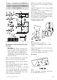
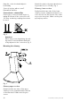
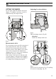
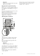
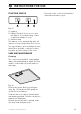
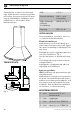
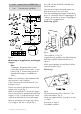
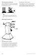
Table Of Contents
- Spiskåpa Tender 722–10/B
- SV Bruksanvisning
- Emhætte Tender 722–10/B
- DA Betjeningsvejledning
- Cooker hood Tender 722–10/B
- GB User instructions
- Kjøkkenhette Tender 722–10/B
- NO Bruksanvisning
- Fig. 13
- Fig. 14
- Fig. 15
- Fig. 16

G
2st
Screws 2.9 x 9.5 TORX T10
I 4st
Screws 3.5 x 6.5 TORX T10
J 1st Full seal damper
Fig. 2
Installation of wall mounts, marking
the wall
Attention!
For total height, distance between the
bottom of the cooker hood and the top
of the chimney, see see dimensions
drawing Fig. 1 When installing with an
extended upper chimney section, see di-
mensions for this.
Mark a centre line A above the cooker whe-
re the cooker hood is to be mounted.
Draw a horizontal reference line B, above
the cooker, Fig. 2.
Place the upper bracket D for the chimney
on the wall, as shown in Fig. 2.
Mark the bracket's screw holes on the wall.
Place the lower bracket D for the chimney
on the wall, as shown in Fig. 2, below the
upper bracket, and mark where the screw
holes should go on the wall.
Mark the screw holes for the mounting of
the cooker hood, C, on the wall, as shown
in Fig. 2.
Drill Ø 3,5 mm holes in the centre of all the
marked points.
Fasten the consoles to the chimney using
the screws F (4.5 x 32 mm).
If the supplied plugs are to be used, drill 6
mm holes. Place wall plugs E in the holes.
Check that the screws and plugs used are
intended for the wall material.
Installing damper unit
Fig. 3
Remove fat filter; see Fig. 12.
Lay the hood and damper unit on a flat
surface.
Attach the damper unit to the cooker fan
using screws I.
Connect the damper control wire to the pin
on top of the damper unit, Fig. 3.
Assembly
Fig. 4
Prior to mounting, screw two screws F into
the pre-drilled holes, Fig. 4.
991.0433.861/126181/2016-02-08 21