
DataSheet FGS201811 en GB
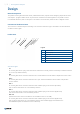
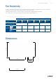
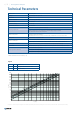
Table Of Contents

6 / 8 | Rectangular Fire Dampers
Technical Parameters
Durability test 250/1000 cycles
Leakage S
a
= 238 m
3
/(h · m2 *) at 25 Pa
Safe position Closed
Possible installations In the wall only (see Tab. 1)
Airow direction Both directions
Allowed air velocity Max. 12 m/s
Side with re protection Both directions
Activating temperature
Manual 74 °C as standard (100°C on demand)
Actuator operated 72 °C as standard (95 °C on demand) by springs in actuator
after the thermo-electrical fuse interruption
Ambient temperature
Excluding temperatures below 0 °C.
Maximum of 60 °C for 72 °C and 74 °C thermo-fuse, maximum 85 °C for 95°C thermo-fuse.
Closing time Actuator driven < 20, manual < 10 s
Indicator closed/open
Manual version ZV; 230 V microswitch in version DV1, DV1-2
Actuator operated – microswitches included in actuator – versions DV7-T, DV9-T and DV9-T-ST
Suitability for environment Only indoor environment Z
2
(internal conditions with humidity lower than 85% RH)
Maintenance Not required/dry cleaning if demanded by law in the country in which the re dampers are installed
Conformity with EC directives
2006/42/ES Machinery Directive
2014/35/EU Low Voltage Directive
2014/30/EU Electromagnetic Compatibility Directive
* NOTE: Nominal surface of the blades (L × H)
p
s
Pa Pressure drop
L
WA
dB(A) A-weighted total sound power level
v m/s Air face velocity
Legend
52 41,5 2,5 3
v (m/s)
800
40
30
20
15
10
6
4
3
1
2
p
S
(Pa)
600
500
400
300
200
150
100
80
60
8
5
50
40
60
30
70
80
129 117 8 106 151413
FGS 200 × 200
FGS 500 × 500
FGS 800 × 1000
L
WA
= 90 dB
Diagram 1: Pressure drop A-weighted total discharged sound power level depending on air face velocity at different duct pressures (PKIS EI120S)