
UserManual FGS201811 en GB

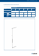
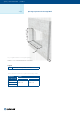
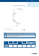
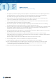
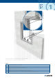
Table Of Contents

Wet
6/XX | User Manual FGS | 2018XX6/22 | User Manual FGS | 201811
1. The supporting construction opening must be prepared in a way described in the section “Opening Preparation”
with the dimensions of L
1
and H
1
(as per Fig. 1 or Fig. 2). Opening surfaces must be even and cleaned off.
The exible wall opening must be reinforced as per the standards for plasterboard walls.
2. Create 2 mounds from the desired lling (2) on the bottom edge of the opening. At the mounds top create
a surface at the desired height for placing the FGS with the help of spirit-level.
3. Insert the mounting frame (1) into the opening so that the ange on the side tted with white board is ush
with the wall surface. This side will be the inspection side (5).
4. Fix the frame in position with screws (3) through the openings in the frame. Make sure there is no skewing
and the diagonals are the same length and there is no torsion deforming the frame.
5. Connect the wires to the connector (see section “Electrical Connections”) on the mounting frame if the FGS is tted
with actuator or position switches in case of manual FGS. Only ZV type of FGS doesn’t need cable connection.
For DV9-T-ST mount the communication unit next to the opening.
6. For FGS with widths greater than 500 mm, it is recommended to use/create a support inside the frame to avoid
any damage, bend to the frame from the weight of the lling.
7. Fill in the area between the wall and the installation frame with plaster or mortar or concrete lling (2),
while making sure the internal surface of the mounting frame is clean from lling. If needed use wooden boards
to create formwork on the inspection side.
First let the plaster or mortar or concrete lling harden and then perform the next steps!
8. After the lling hardens, remove the installation frame support and framework.
9. If needed, uncover and clean the internal surfaces of the installation frame after installation.
10. Insert the closed FGS body into the installation frame, while joining the connectors and x both the upper
and lower side of the FGS with screws DIN 7504M-SR 4.2 × 25 (6; screws are included in the packaging
- the amount depends on nominal dimensions of the FGS)
11. Check the FGS functionality, following the instruction from section “FGS Functionality Check”
Wet Installation
Using Plaster/Mortar/Concrete Filling